| Sun Ultra 40 Workstation Service Manual |
| C H A P T E R 6 |
|
Replacing Storage Devices |
This chapter provides removal and installation procedures for storage devices.
The procedures described in this chapter are written for workstation service providers and system administrators.
This chapter contains the following sections:

|
Caution - To prevent equipment damage, review the safety information in Chapter 4before you perform any replacement procedure. Additional cautions, warnings, and instructions are provided in the Ultra 40 Workstation Safety and Compliance Guide, part number 820-0122. The document is available at:
http://www.sun.com/documentation |
The Ultra 40 Workstation supports up to four hard drives. The Ultra 40 M2 supports up to eight hard drives. The hard drives slide into the hard drive bay. The hard drives are labeled HDD0 through HDD3 (or HDD7). HDD0 is the default boot drive. See FIGURE 6-1.
TABLE 6-1 lists the hard drive specifications.
If you are not removing an existing hard drive, proceed to Section 6.1.2, Installing a Hard Drive.
1. Power off the system, open and position the chassis, and remove the access panel.
Refer to Section 4.3, Preparing the Workstation for Servicing.
2. Slide the hard drive release tab toward the front of the system.
The hard drive handle pops up. See FIGURE 6-1.
3. Grasp the hard drive handle and pull the hard drive out of the hard drive bay.
See FIGURE 6-1.

FIGURE 6-1 Removing a Hard Drive (Ultra 40 Shown)
4. Place the hard drive aside on an antistatic mat.
1. Power off the system, open and position the chassis, and remove the access panel.
Refer to Section 4.3, Preparing the Workstation for Servicing.
| Note - By default, the system boots from the hard drive in HDD0. If there is no drive there, it boots from the drive in HDD1. |
2. Remove the new hard drive from its packaging.
Refer to the hard drive documentation for configuration instructions.
See FIGURE 6-2.
4. Slide the hard drive into the hard drive bay.
5. Close the latch on the hard drive until it clicks and is secure.

FIGURE 6-2 Installing a Hard Drive (Ultra 40 Shown)
6. If you are finished working, install the side cover and the access panel, power on the system, and verify the installation.
Refer to Section 8.1, Reassembling the Workstation.
| Tip - Boot the workstation with the -r option, so that the Solaris operating system can reconfigure itself for the new component. See Section 8.1, Reassembling the Workstation. |
This section provides procedures for removing and installing the hard drive backplane and signal cable.
On Sun Ultra 40 M2 systems, if you have a single hard drive backplane, and you are adding a second hard drive backplane, go directly to Section 6.2.2, Installing the Hard Drive Backplane and Signal Cable.
The hard drive backplane power cable is an integral part of the power supply. To replace it, you must replace the power supply as described in Section 7.2, Removing and Replacing the Power Supply. Normally, this is not necessary when replacing the hard drive backplane and signal cable.
Sun Ultra 40 systems have a single hard drive backplane that supports HDD0 through HDD3.
Sun Ultra 40 M2 systems have an optional second hard drive backplane that supports HDD4 through HDD7.
To remove the hard drive backplane and signal cable:
1. Power off the system, open and position the chassis, and remove the access panel.
Refer to Section 4.3, Preparing the Workstation for Servicing.

FIGURE 6-3 Disconnecting the Cables From the Hard Drive Backplane for Ultra 40

FIGURE 6-4 Disconnecting the Cables From the Hard Drive Backplane for Ultra 40 M2
Refer to Section 6.1, Replacing a Hard Drive.
3. Disconnect the hard drive signal cable from the connector of the hard drive backplane.
For the Ultra 40, it is connector J4.
4. Disconnect the power cable from the corresponding hard drive backplane. See FIGURE 6-3 or FIGURE 6-4:
| Note - P4 has a splitter; one part goes to the hard drive backplane, and the other part goes to the motherboard. Disconnect only the part that goes to hard drive backplane. |
5. Using a No. 2 Phillips screwdriver, remove the two screws that secure the hard drive backplane.
6. If you are replacing the hard drive signal cable, disconnect it from the SAT0 connector on the motherboard.
| Note - The hard drive power cable is part of the power supply assembly. To replace it, you must replace the power supply. |
7. Slide the hard drive backplane toward the back of the system (toward the motherboard) until the studs protrude through the wide side of the mounting slots.
8. Lift the hard drive backplane out and away from the chassis.
To install the hard drive backplane and signal cable:
1. Remove the new hard drive backplane and the hard drive signal cable from the packaging.
2. Verify that the master/slave switch is in the correct position. See FIGURE 6-5.
b. Verify that the switch is in the correct position, and correct it if it is not.
| Note - This switch might not be present on Sun Ultra 40 systems. |

FIGURE 6-5 Master/Slave Switch on HDD Backplane
3. If you are adding a second backplane to an Ultra 40 M2, remove the filler panel. If not, proceed to Step 4.
a. Release the two latches by pressing them towards the front of the system.
See FIGURE 6-6.
b. Swing the filler panel out (1) then lift it away (2).
See FIGURE 6-7.

FIGURE 6-6 Release the Latches

FIGURE 6-7 Swing The Panel Out
4. Place the new hard drive backplane in the chassis so that the studs protrude through the fat end of the slots.
5. Slide the backplane toward the motherboard so that the studs hold the backplane securely in place.
6. Using a No. 2 Phillips screwdriver, replace the two screws that secure the hard drive backplane.
7. To reconnect the hard drive signal cable:
Route the cable under the hard drive power cable in such a way that it will not interfere with the fan tray.
For the Ultra 40, it is connector J4.
| Note - For HDD0 through HDD3, it is connector J22. For HDD4 through HDD7, it is connector J11. |
8. Reconnect the power cable to the corresponding hard drive backplane. See FIGURE 6-3 or FIGURE 6-4:
| Note - P4 has a splitter; one part goes to the hard drive backplane and the other part goes to the motherboard. The part that goes to the motherboard should have remained connected. |
9. Inspect the cabling to verify that the signal and power cables are both secure at the backplane and that the signal cable is secure at the motherboard.
See FIGURE 6-2 and refer to Section 6.1.2, Installing a Hard Drive.
11. Install the side cover and the access panel, power on the system, and verify the installation.
Refer to Section 8.1, Reassembling the Workstation.
This section describes how to change the I/O module and DVD drive and their associated cables. The I/O module and DVD drive are a single assembly mounted in the removable media bay in the front of the chassis.
Use the following procedures to remove and replace the I/O module, and associated cables (the audio power cable, USB signal cable, and the DVD dual drive signal cable).
1. Power off the system, open and position the chassis, and remove the access panel.
Refer to Section 4.3, Preparing the Workstation for Servicing.
2. Using the handle, pull the fan tray from the chassis and set it aside.
See FIGURE 7-1 for details.
1. Disconnect the following cables from back of the I/O module (1):
See FIGURE 6-8 for (1) through (5).

FIGURE 6-8 I/O Module Assembly and Cables
2. Push in the I/O module release latch (2).
3. Pull the I/O module out from the front of the workstation chassis (3).
4. Place the I/O module down on an antistatic mat.
| Note - Do not attempt to remove the bezel from the front of the I/O module. |
5. Remove the new I/O module from its packaging.
1. Unsnap the cable clamp that secures the USB signal cable and the DVD dual drive signal cable to the chassis.
Pull the clamp gently away from the chassis at the top, as shown in FIGURE 6-9.

FIGURE 6-9 Unsnapping the Cable Clamp
2. Disconnect the USB signal cable from the motherboard connector FP1.
3. Remove the old USB signal cable and route the new cable in exactly the same way.
Route the cable from the back of the I/O module, under the cable clamp, to the motherboard.
4. Connect the new USB signal cable to the motherboard connector FP1.
5. Disconnect the old DVD dual drive signal cable from the motherboard DVD connector.
6. Remove the old cable and route the new cable in exactly the same way.
Route the cable underneath the other motherboard cables to the top of the chassis. Do not unfold the cable or add any folds to it.
7. Connect the new DVD dual drive signal cable to the motherboard connector labeled DVD.
1. Disconnect the I/O power cable from motherboard connector FP3.
2. Unfasten the cable ties that secure the I/O power cable to the disk drive bay.
See FIGURE 6-10.

FIGURE 6-10 Unfastening the I/O Power Cable Ties
3. Route the replacement cable in the same way, from the I/O board, through the cable ties on the side of the disk drive bay, to motherboard connector FP3.
4. Fasten the I/O power cable to motherboard connector FP3.
1. Slide the I/O module back into the front of the workstation chassis.
2. Connect the following cables to the I/O module:
See FIGURE 6-8.
3. Inspect the cabling to verify that all connectors are firmly connected at both ends.
4. Slide the fan tray back into the chassis.
See FIGURE 7-1 for details.
5. Install the side cover and the access panel, power on the system, and verify the installation.
Refer to Section 8.1, Reassembling the Workstation.
| Tip - Boot the workstation with the -r option, so that the Solaris operating system can reconfigure itself for the new component. See Section 8.1, Reassembling the Workstation. |
If you want to replace the SATA drives with SAS drives, use the following procedure. You will need to order a SAS installation kit, that includes a SAS controller card (SG-PCIE8SAS-Z, LSI-based), cable kit, and SAS HDDs.
The following procedure describes how to modify the current installation and install the SAS components:
1. Power off the system, open and position the chassis, and remove the access panel.
Refer to Section 4.3, Preparing the Workstation for Servicing.
2. Using the handle, pull the fan tray from the chassis and set it aside.
See FIGURE 7-1 for details.
3. Remove the current SATA hard drive(s) from the server.
4. Remove and discard the cables currently connected to the HDD backplanes and motherboard connectors. See FIGURE 6-3.
| Note - If there is a card in the PCI-E0 slot, you should remove and relocate it as described in Section 5.4, Replacing PCI Cards. |
| Note - Connect the cables before inserting the SAS card in the PCI-E0 slot. |
a. For the Sun Ultra 40, see FIGURE 6-11 and connect the following cables:
i. Connect the large connector cable to the HDD backplane.
ii. Using the SAS cable kit, connect the SAS cables to the SAS card connectors before the SAS card is installed.
b. For the Sun Ultra 40 M2, see FIGURE 6-11 and connect the following cables:
i. Connect the shorter RED cable (from the lower backplane) to the card connector labeled "Port 0..3"
ii. Connect the longer ORANGE cable (from the upper backplane) to the card connector labeled "Port 4..7". If no upper backplane is present, leave this cable to dangle.
i. If you ordered an external LED cable, connect it from the PCI card to the connector to the right of the battery.
6. Locate the PCI-E0 card slot.
The SAS card is restricted to slot PCI-E0. This restriction is for cable routing purposes only and will not interfere with high end graphics cards that would use the upper slots
See FIGURE 5-11 and FIGURE 5-12 for PCI card locations.
7. Use the No. 2 Phillips screwdriver to remove the chassis filler panel from the PCI card slot.
See FIGURE 5-13. Place the screw aside in a container.
8. Insert the SAS card into the PCI card slot.
To keep the cable out of the air stream, you should route the cable between the power supply and PCI-E0 slot.
11. Install the SAS hard drives.
12. If you are finished working, install the side cover, the access panel, power on the system, and verify the installation.
Refer to Section 8.1, Reassembling the Workstation.
| Tip - Boot the workstation with the -roption, so that the Solaris operating system can reconfigure itself for the new component. See Section 8.1, Reassembling the Workstation. |

FIGURE 6-11 Installing a SAS Card in the Sun Ultra 40

FIGURE 6-12 Installing a SAS Card in the Sun Ultra 40 M2
If you’ve upgraded the workstation to SAS drives and later need to replace the SAS controller card (SG-PCIE8SAS-Z, LSI-based), do the following:
1. Power off the system, open and position the chassis, and remove the access panel.
Refer to Section 4.3, Preparing the Workstation for Servicing.
2. Using the handle, pull the fan tray from the chassis and set it aside.
See FIGURE 7-1 for details.
3. Disconnect the SAS cables from the SAS controller card to be replaced.
See FIGURE 6-12 for details.
4. Remove the SAS controller card from the system PCI-E0 slot and install the new one in the same PCI-E0 slot.
5. Reconnect the SAS cables to the new SAS controller card.
See FIGURE 6-12 for details.
6. Re-install the side cover, the access panel, power on the system, and verify the installation.
Refer to Section 8.1, Reassembling the Workstation.
7. Boot the workstation with the -r option, so that the Solaris operating system can reconfigure itself for the new component. See Section 8.1, Reassembling the Workstation.
8. If the workstation’s SAS drives were previously configured in a RAID using the old SAS controller card, you will need to re-activate the existing array for use with the new SAS controller card. Reboot the workstation.
9. When the BIOS loads during boot and you see the message about the LSI Configuration Utility, press Ctrl-C to start the LSI BIOS Configuration Utility.
10. At the Adapter List screen, use the arrow keys to select the SAS adapter, then press Enter.
The Adapter Properties screen dispays.
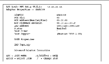
FIGURE 6-13 Example Adapter Properties Screen
11. Select the RAID Properties option.
The properties of the current volume are displayed.
12. Select the Manage Array option and press Enter.
The Manage Array screen is displayed.
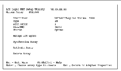
FIGURE 6-14 Example Manage Array Screen
13. At the Manage Array screen, select Activate Array.
14. Press Y to proceed with the activation.
After a pause, the array will become active.
15. Follow the on-screen instructions to exit the utility (save as prompted).
| Sun Ultra 40 Workstation Service Manual | 820-0123-13 |
Copyright © 2008, Sun Microsystems, Inc. All Rights Reserved.