| Skip Navigation Links | |
| Exit Print View | |

|
Sun Fire X4800 Server Product Documentation |
Installing the Server In the Rack Using the Universal Rack Mounting Kit
Contents of the Universal Rack Mounting Kit
Installing the Server in a Rack Using the Universal Rack Mounting Kit
How to Remove Components to Reduce Weight
How to Replace the Components in the Server
How to Install the Rack Mounting Hardware in a Square-Hole Rack
How to Insert the Server Into the Rack
Installing and Removing the Universal Rack Mounting Kit Shipping Brackets
How to Install the Universal Rack Mounting Kit Shipping Brackets
How to Remove the Universal Rack Mounting Kit Shipping Brackets
The rack mounting kit consists of adapter brackets, rear braces, shelf rails, cage nuts, and screws.
 | Caution - The server weighs about 180 pounds (100 kg) when fully loaded with components. To reduce the risk of serious personal injury or equipment damage, use a mechanical lift to install the server into the rack. If a lift is not available, remove components as described in How to Remove Components to Reduce Weight. This reduces the weight of the server to 80 pounds (45 kg). Always load equipment into a rack from the bottom up so that it does not become top-heavy and tip over. Deploy your rack’s anti-tilt bar to prevent the rack from tipping during equipment installation. |
Note - To install rack mounting hardware in square-hole racks, see How to Install the Rack Mounting Hardware in a Square-Hole Rack.
This task uses the following screws and connectors:
|
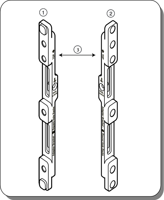
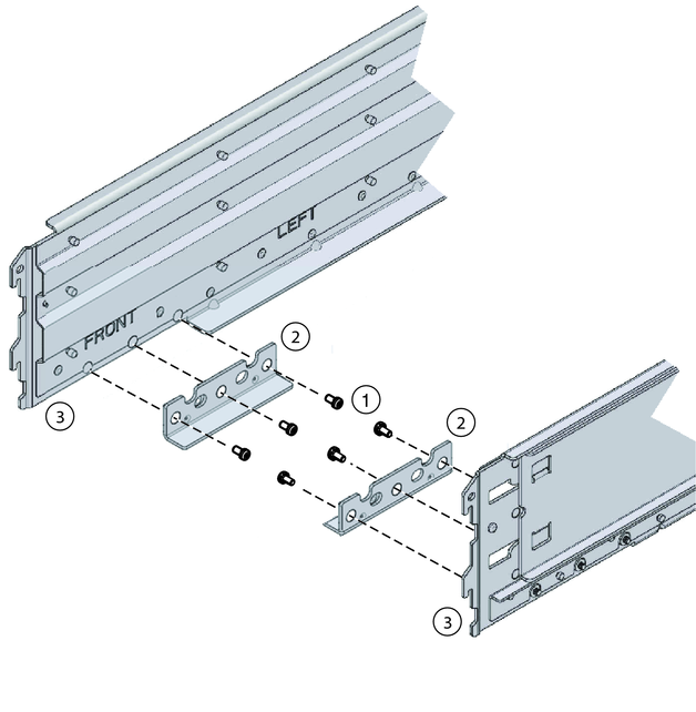
The server ships with two sets of adapter brackets: one for racks with square holes (1), and one for racks with round holes (2). The adapter brackets for square-hole racks (1) have threads. The adapter brackets for round-hole (tapped) racks (2) do not. See the following figure.
Note - Arrows on the adapter brackets (3) indicate how they should be oriented. Be sure to install all brackets with the “Top” arrow (3) pointing up.
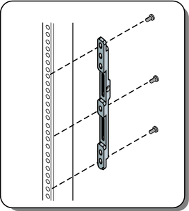
Place the adapter brackets so that the bottom of the adapter bracket is aligned with the bottom of the (5RU) space where the server will go, and that the arrow labelled “top” points up.
Use three M6 x 12 or 10-32 x 10 screws for each side. Pass the screws from the inside of the rack, through the adapter bracket, and into the threads on the post.
Note - The accessory box includes a printed template that you can use to help align the adapter brackets.
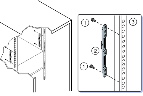
Place the adapter brackets so that the bottom of the adapter bracket is aligned with the bottom of the (5RU) space where the server will go, and that the arrow labelled “top” points up.
Pass two screws (1) from the inside of the rack, through the top and bottom holes in the adapter bracket (2), and thread them into the post (3).
Note - Do not use the center screw in the adapter bracket. It is reserved for the optional shipping bracket kit described in Installing and Removing the Universal Rack Mounting Kit Shipping Brackets.
For M6 racks, use two M6 x 12 screws per side.
For 10-32 racks, use two 10-32 shoulder screws per side.
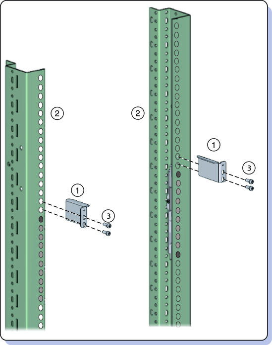
Use either two M6 x 16 or two 10-32 x 10mm screws (3) per side.
Before tightening the screws, slide the braces (1) up as far as they will go. The holes on the braces are oval-shaped so they can move a little up and down when the screws are loose.
You must remove the shelf extenders before installing the server in the rack. They are used for other products.
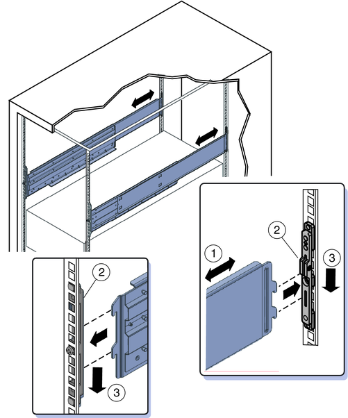
The shelf rails expand (1) to fit the rack, then slip into the slots on the adapter brackets (2), and drop into place (3).
Be certain to place the shelf rails in the proper orientation. They are labelled “FRONT LEFT” and “FRONT RIGHT”.
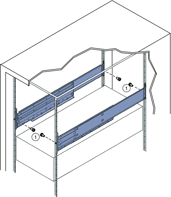
These prevent the shelf rails from accidentally lifting out of the adapter brackets.
Next Steps