This chapter describes how to set up the Sun Fire X4450 server hardware. It includes the following topics:
Tools and Equipment Needed
To install the system, you need the following tools:
- #2 Phillips screwdriver
- ESD mat and grounding strap
- Pencil, stylus, or other pointed device, for pushing front panel buttons
You also need a system console device, such as one of the following:
- Sun workstation
- ASCII terminal
- Terminal server
Installation Process Flowchart
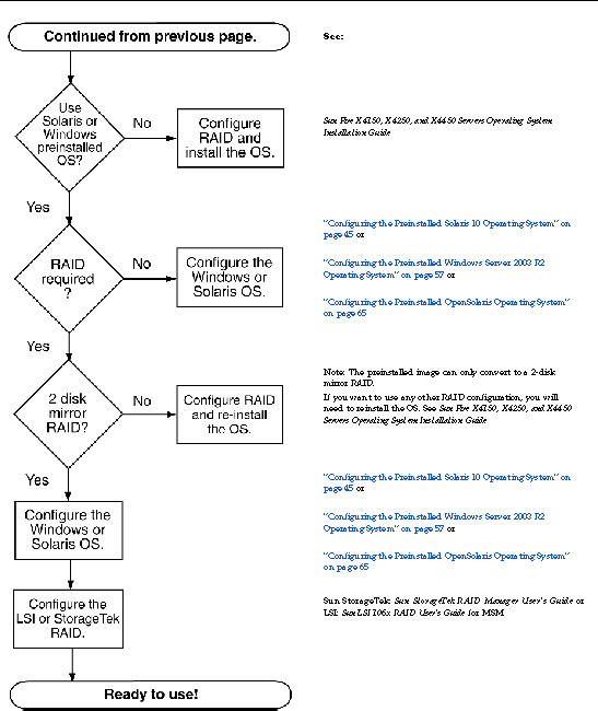
To install a typical server, follow the flowchart in FIGURE 1-1 and FIGURE 1-2.
FIGURE 1-1 Sun Fire X4450 server Installation Process (Part 1)
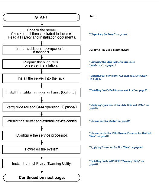
FIGURE 1-2 Sun Fire X4450 server Installation Process (Part 2)
Unpacking the Boxes
Unpack all server components from the packing cartons.
Package Contents Inventory
The following items should be packaged with the Sun Fire X4450 server:
- Sun Fire X4450 server
- Sun Fire X4450 server accessory kit, including the following documentation:
- Sun Fire X4150, X4250, and X4450 Servers Getting Started Guide
- Important Safety Information for Sun Hardware Systems
- Additional license, safety, and registration documentation
- DB9-RJ45 adapter (for serial system management port)
- Optional rackmount kit
- Optional cable management kit
Power cables, keyboard, and mouse are packaged separately from the other items.
Options
The documentation and CD kit is a separate orderable option. This kit currently includes the following items:
- Sun Fire X4450 Server Installation Guide (this document)
- SunVTS Diagnostics CD
- Sun Fire X4450 Server Tools and Drivers DVD (includes drivers and additional software)
- Sun Installation Assistant CD
Standard server components are installed at the factory. However, ordered options such as additional memory or PCI-e cards are shipped separately. If possible, install optional components before installing the server in a rack.
ESD Precautions
Electronic equipment is susceptible to damage by static electricity. Use a grounded antistatic wriststrap, footstrap, or equivalent safety equipment to prevent electrostatic damage (ESD) when you install or service the server.

|
Caution - To protect electronic components from electrostatic damage, which can permanently disable the system or require repair by Sun service technicians, place components on an antistatic surface, such as an antistatic discharge mat, an antistatic bag, or a disposable antistatic mat. Wear an antistatic grounding strap connected to a metal surface on the chassis when you work on system components.
|
Sun Fire X4450 Server Description
This section shows the Sun Fire X4450 server front and back panel features.
Front Panel Features
See FIGURE 1-3 and TABLE 1-1 for the front panel features.
FIGURE 1-3 Front Panel - 8 drive configuration shown
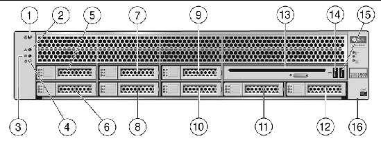
TABLE 1-1 Front Panel Legend
|
Label
|
Item
|
Label
|
Item
|
|
1
|
Locator LED/Locator button: white
|
9
|
Hard disk drive 5 (optional)
|
|
2
|
Service Required LED: amber
|
10
|
Hard disk drive 4 (optional)
|
|
3
|
Power/OK LED: green
|
11
|
Hard disk drive 6 (optional)
|
|
4
|
Power button
|
12
|
Hard disk drive 7 (optional)
|
|
5
|
Hard disk drive 1 (optional)
|
13
|
DVD drive (optional)
|
|
6
|
Hard disk drive 0 (optional)
|
14
|
USB 2.0 connector (2)
|
|
7
|
Hard disk drive 3 (optional)
|
15
|
USB 2.0 connector (3)
|
|
8
|
Hard disk drive 2 (optional)
|
16
|
Fault LEDs: amber
Top open (Check fan status)
Power supply (PS)
Over temperature warning
|
Back Panel
See FIGURE 1-4 and TABLE 1-2 for the back panel features.
FIGURE 1-4 Back Panel
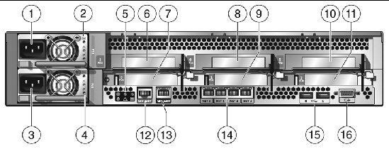
TABLE 1-2 Back Panel Legend
|
Label
|
Item
|
Label
|
Item
|
|
1
|
Power supply unit 1 connector
|
6
7
8
9
10
11
|
PCI-express slot (3)
PCI-express slot (0)
PCI-express slot (4)
PCI-express slot (1)
PCI-express slot (5)
PCI-express slot (2)
|
|
2
|
Power supply unit 1 status indicator LEDs
|
|
|
- Power Supply OK: green
- Power Supply Fail: amber
- AC OK: green
|
|
3
|
Power supply unit 0 connector
|
12
|
Serial management/RJ-45 serial port
|
|
4
|
Power supply unit 0 status indicator LEDs:
- Power Supply OK: green
- Power Supply Fail: amber
- AC OK: green
|
13
|
Service processor (SP) network management NET MGT port
|
|
5
|
System status LEDs:
|
14
|
Gbit Ethernet ports NET 0, 1, 2, 3 (Intel)
|
|
|
- Power: green
- Attention: amber
- Locate: white
|
15
|
USB 2.0 ports (0, 1)
|
|
|
|
16
|
HD15 video connector (analog VGA)
|
| Sun Fire X4450 Server Installation Guide
|
820-2709-13
|
   
|
Copyright © 2009 Sun Microsystems, Inc. All rights reserved.