| Sun StorEdge 3000 Family Installation, Operation, and Service Manual |
| A P P E N D I X B |
|
Cabling JBODs |
You can connect a Sun StorEdge 3320 JBOD (Just a Bunch of Disks, no controller) array directly to a host server.
This appendix covers the following topics:

|
Caution - When you connect or disconnect SCSI cables, the host I/O must be inactive. |
|
|
Caution - You can replace the I/O module or change its cables while the array is powered on but the SCSI host buses connected to the array must be inactive. |
Limitations affecting the Sun StorEdge 3320 SCSI JBOD array are listed below:
The SCSI specification states that the maximum bus length for Ultra3 SCSI is 12 meters (39.4 feet) for multidrop connections. The Sun StorEdge 3320 JBOD arrays use a multidrop implementation. The ports on each channel are connected to the same physical SCSI bus.
Taking into account the internal bus length of .5 meters (1.6 feet), and the internal SCSI bus length of the host, the maximum SCSI bus length for each channel is 12 meters (39.4 feet) when connected to an LVD host adapter.
You must ensure that the length of all cables to any connected nodes, as well as the internal bus length of .5 meters (1.6 feet) internal to the Sun StorEdge 3320 JBOD array and the internal bus length of the host, is less than 12 meters (39.4 feet) in total. Also include the jumper cable length of .3 meters (.98 feet) if the JBOD is being used in a single-bus configuration.
The longest Ultra3 cable qualified by Sun is 10 meters (32.8 feet) in length.
When connected to single-ended host adapters, the longest supported bus length per channel is 1.5 meters (4.9 feet).
To connect a JBOD in a single-bus configuration to a single host, connect the following ports:
|
|
Caution - Beforeyou disconnect a cable from the array, the host bus on that cable must be inactive. |

FIGURE B-1 A Single-Bus JBOD with One Host Connection (Rear View)
The following table shows the default physical drive IDs for a 12-drive JBOD when you set up a single-bus configuration. The physical drive IDs are 0-13, with IDs 6 and 7 reserved for host HBA connections
| Note - A single-bus JBOD configuration can only be used with one host. To connect two hosts, use a split-bus JBOD configuration. |
There are two important features to note with the split-bus, single-initiator JBOD configuration:
Single-initiator mode has only one host connection on a SCSI channel.
FIGURE B-2 shows a split-bus JBOD with two host connections using one host connection to each channel (single-initiator mode). In this example, the array can be connected to two hosts or to two ports on one host. For the single host configuration, this is an efficient way to provide mirroring capability for the single host.

FIGURE B-2 Split-Bus Single-Initiator JBOD Configuration
In the previous split-bus, single-initiator mode example, the physical drive IDs are 8 to 13 on each channel. In the following table, A and B indicate the two host channels. The table shows the IDs assigned to each channel in the split-bus configuration.
To connect a split-bus JBOD, perform the following steps.
1. Stop any I/O on the host bus that will have a cable installed on the bus.
2. Connect each JBOD port to a host.
|
|
Caution - The lower input ports of the JBOD must have a host connection or external terminator to maintain SCSI bus integrity. |
|
|
Caution - Before you disconnect a cable from the array, the host bus on that cable must be inactive. |
There are two important features to note with the split-bus, multi-initiator JBOD configuration:
Multi-initiator mode has more than one host connection on a SCSI channel.
FIGURE B-3 shows a multi-initiator, split-bus configuration where each host is connected to each host channel. This configuration is common for failover protection in a network cluster environment.
When you remove one or more host cables for maintenance purposes, insert an external terminator into each empty port to maintain the physical drive IDs for the active host connections.
| Note - You can replace the I/O module or change its cables while the array is powered on, but the SCSI host buses connected to the array must be inactive. |

FIGURE B-3 Dual-Host, Split-Bus Multi-Initiator JBOD Configuration
In this configuration, the split-bus, multi-initiator mode creates physical drive IDs 0 to 5 on each channel as shown in TABLE B-3.
To connect a split-bus JBOD to two hosts, perform the following steps.
1. Stop any I/O on the host bus that will have a cable installed on the bus.
2. Connect each JBOD port to a host as shown in FIGURE B-3.
The lower input ports of the JBOD must have a host connection or external terminator to maintain SCSI bus integrity.
| Note - Before you disconnect a cable from the array, the host bus on that cable must be inactive. |
The following software management tools are provided on the Sun StorEdge 3000 Family Software and Documentation CD for your array.
For details on how to install Sun StorEdge Configuration Service, Sun StorEdge Diagnostic Reporter, or Sun StorEdge CLI software, refer to the Sun StorEdge 3000 Family Software Installation Guide.
Sun StorEdge Configuration Service supports the Sun StorEdge 3320 SCSI array. It also supports, to a limited degree, standalone Sun StorEdge 3320 SCSI JBOD arrays. Since standalone JBOD arrays do not have a RAID controller to manage the disks, this software support for JBODs is limited to the following functions:
Refer to the Sun StorEdge 3000 Family Configuration Service User’s Guide for information about using these functions with JBOD arrays.
Use JBOD support only when you have a SCSI array connected directly to a host. This enables you to monitor peripheral device conditions and events.
| Note - Enabling JBOD support might impact I/O performance. |
To monitor peripheral device condition and events for a JBOD device from the Sun StorEdge Configuration Service Console, you first need to enable JBOD support.
1. Choose View  Agent Options Management.
The Agent Options Management window is displayed.
2. Select the Enable JBOD Support checkbox.
3. To immediately display the JBOD array in the main window, you must probe for new inventory. Choose View View Server and click Probe.
The JBOD array is displayed in the main window.
In a single-bus configuration, both ports of the JBOD array are connected to one HBA on the server, as shown in the following example:
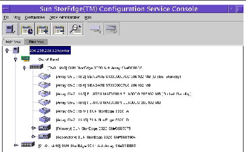
FIGURE B-4 Single-Bus Configuration
In Sun StorEdge Configuration Service, to view environmental component and alarm characteristics, use the View Enclosure window or, for some components, the main window.
You can also view environmental and drive components using the Sun StorEdge CLI show enclosure-status command. For details, refer to the Sun StorEdge 3000 Family CLI User’s Guide.
In the main window, device states are color-coded and symbol-coded so that it is easy to identify when a device is in a state that requires attention. The status is propagated along the device tree, enabling you to trace a failure down to the device level. See TABLE B-4 for device status details.
To view the cause of a critical or degraded device status, review the event log. For details on the event log, refer to the Sun StorEdge 3000 Family Configuration Service User’s Guide.
The View Enclosure window displays the component and alarm characteristics for a JBOD device. The window displays the status for environmental components including the fan, power supply, and temperature sensor.
To view the environmental component and alarm characteristics of a SCSI array from the Sun StorEdge Configuration Service Console, perform the following steps.
1. Select the event-monitoring unit (EMU) icon .
.
2. Choose View View Enclosure.
To display FRU ID information, click View FRU.

FIGURE B-5 View Enclosure Dialog Box
Sun StorEdge Diagnostic Reporter supports standalone JBOD arrays. However, triggered event notification is limited to environmental and hard drive failures.
The Sun StorEdge CLI supports JBOD arrays. However, because JBOD arrays do not have a RAID controller to manage the disks, this command-line interface support is limited to the following commands:
Refer to the Sun StorEdge 3000 Family CLI User’s Guide for information about using these commands.
For instructions on how to download firmware to disk drives in a JBOD directly attached to a host, refer to the README file in the patch that contains the firmware.
Use your standard host system disk management utilities for all disk management in a JBOD array, such as partitioning and formatting. Refer to your host system documentation for more information about disk management.
For maintenance and troubleshooting information, see Section B.13, Troubleshooting Sun StorEdge 3320 SCSI JBOD Arrays.
To enable VERITAS Dynamic Multipathing (DMP) support on VERITAS Volume Manager Version 3.2, ensure the HBA device SCSI initiator IDs are unique and then start the system. Perform the following steps.
1. Create a single-bus, multi-initiator configuration that links two cables to two different HBAs.
For details about creating a single-bus multi-initiator configuration, see Section Note -, A single-bus JBOD configuration can only be used with one host. To connect two hosts, use a split-bus JBOD configuration..
2. Stop the server and at the OpenBoot PROM (OBP) Monitor ok prompt, type:
3. Issue the remaining commands on only one of the paths.
4. Edit or create the nvramrc to set the SCSI-initiator-id to a non-conflicting ID for these devices. The information returned from the probe-scsi-all command identifies the IDs that are currently used and unavailable for assignment.
ok nvedit 0: probe-all 1: cd /pci@6,4000/scsi@3 *** your path information here *** 2: 6 " scsi-initiator-id" integer-property 3: device-end 4: banner (Ctrl-c) |
6. Store the nvramrc by typing:
7. Set the system to use the nvramrc and reset auto-boot by typing:
8. Reset the configuration by typing:
9. Reboot the hosts. A system reboot is required to implement these changes.
This section describes troubleshooting procedures and error messages you can use to isolate configuration and hardware problems. For additional troubleshooting information, see Chapter 7.
Follow this sequence of general steps to isolate software and configuration issues.
1. Look for storage-related messages in /var/adm/messages and identify any suspect JBOD arrays.
2. Check your Sun StorEdge Configuration Service console for alerts or messages.
3. Check revisions of software package, patches, and hardware.
4. Verify correct device file paths.
5. Check any related software, configuration, or startup files for recent changes.
Search SunSolve Online for any known related bugs and problems at: http://sunsolve.sun.com
When a problem is not otherwise reproducible, suspect hardware might need to be replaced. Always make only one change at a time and carefully monitor results. When possible, it is best to restore the original hardware before replacing another part to eliminate the introduction of additional unknown problem sources.
After hardware replacement, a problem can usually be considered solved if it does not resurface during a period equal to twice its original frequency of occurrence. For example, if a problem was occurring once a week on average before a potential fix was made, running two weeks without seeing the problem again suggests a successful fix took place.
Troubleshooting hardware problems is usually accomplished by an FRU isolation sequence that uses the process of elimination. Set up a minimal configuration that shows the problem and then replace elements in this order, testing after each replacement until the problem is solved:
Often you can also find out what does cause a hardware problem by determining the elements that do not cause it. Start out by testing the smallest configuration that does work, and then keep adding components until a failure is detected.
To view error messages reported by JBODs or expansion units, use any of the following:
For more information about replacing the chassis, I/O module, or controller, refer to the Sun StorEdge 3000 Family FRU Installation Guide.
Before you begin troubleshooting a JBOD or expansion unit, check the cables that connect the host to the JBOD or expansion unit. Look for bent pins, loose wires, loose cable shields, loose cable casing, and any cables with 90 degree or more bends in them. If you find any of these conditions, replace the cable.
The FIGURE B-6 flowchart provides troubleshooting procedures specifically for JBODs and expansion units. For additional troubleshooting flowcharts, see Section 7.7.1, Power Supply and Fan Module and Section 7.7.2, Drive LEDs.
For an IBM AIX operating system, the event logs are not logged by default. You might need to change /etc/syslog.conf to enable it to write to a log file.
1. Modify /etc/syslog.conf to add the following line:
2. Make sure the file that is specified in the added line exists.
If it does not exist, you must create it. For example, in the above configuration, you would create a file named /tmp/syslog.
3. Change to /tmp/syslog and restart the syslog by typing:

FIGURE B-6 JBOD or Expansion Unit Troubleshooting Flowchart, 1 of 4

FIGURE B-7 JBOD or Expansion Unit Troubleshooting Flowchart, 2 of 4

FIGURE B-8 JBOD or Expansion Unit Troubleshooting Flowchart, 3 of 4

FIGURE B-9 JBOD or Expansion Unit Troubleshooting Flowchart, 4 of 4
| Sun StorEdge 3000 Family Installation, Operation, and Service Manual | 819-1274-14 |
Copyright © 2009 Sun Microsystems, Inc. All rights reserved.


