| SPARC Enterprise M8000/M9000 Servers Overview Guide |
| C H A P T E R 1 |
|
System Overview |
This chapter provides an overview of features, specifications, and configurations of the SPARC Enterprise M8000/M9000 servers.
This section describes the features and appearances of M8000/M9000 servers.
M8000/M9000 servers have been developed as UNIX servers using a symmetric multi-processing (SMP) architecture. Each of these systems merges mainframe technologies for high reliability, and the associated know-how accumulated over time, with the high-speed technologies of super computers and the openness of UNIX server development.
If a problem occurs during operation, the errors causing them can be corrected or isolated without stopping the system. This feature minimizes problems in many cases, thereby improving job continuity.
Each of the M8000/M9000 servers contains one or more multicore SPARC64 VI, SPARC64 VII, and SPARC64 VII+ processors. They can operate as multiple servers that permit flexible use of resources, including more efficient execution of job operations. In the M8000/M9000 servers, the SPARC64 VI, SPARC64 VII, and SPARC64 VII+ processors can be mounted in combination.
Each server consists of a cabinet containing various mounted components, a front door, rear door, and side panels as parts of the server structure. An operator panel is mounted on the front door and is always accessible. Take special care in handling and storing the dedicated key that is provided for the front door and the operator panel.
FIGURE 1-1 through FIGURE 1-3 show exterior views of the servers.
FIGURE 1-1 M8000 Server (Front View)
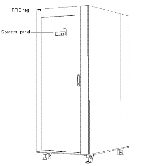
FIGURE 1-2 M9000 Server (Base Cabinet Only)
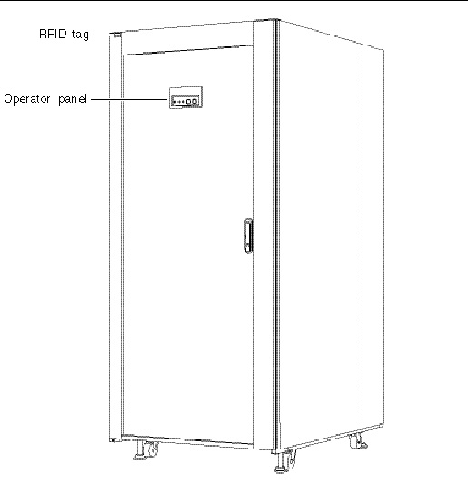
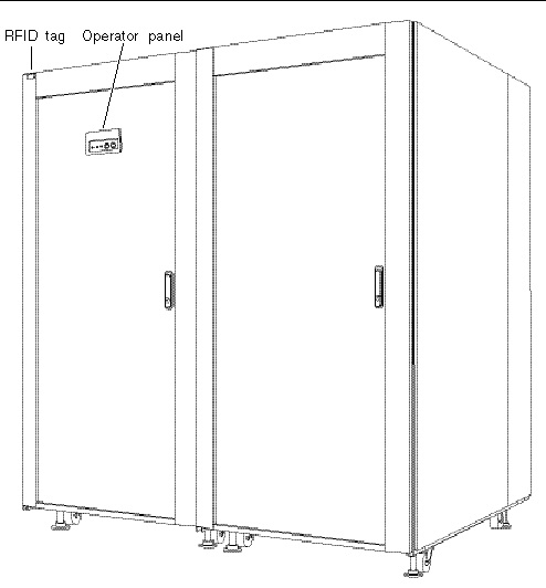
The expansion cabinet is an M9000 option connected to the M9000 (type for the base cabinet only).
FIGURE 1-3 M9000 Server (With an Expansion Cabinet)
M8000/M9000 servers have the following features:
These processors provide superior performance, due to their high scalability allowing expansion to up to 64 dual-core CPU modules, and technologies enabling high-speed arithmetic operations and data transfers.
Reliability and availability are enhanced with Error Checking and Correction (ECC) data protection and instruction retry.
As faster and higher-performing CPU modules become available, they can be added to or replace existing installed CPU modules to further improve performance.
The system uses symmetric multiple-processing (SMP), so each CPU can access any part of system memory regardless of its mounting location. Adding more CPUs does not affect memory access to any of the installed CPUs.
The high-speed crossbar-type system bus that provides high-speed wide-band data transfer maximizes the performance of the SPARC64 VI/SPARC64 VII/SPARC64 VII+ processors.
ECC functionality protects data on all system buses and in memory, so that any errors in data are automatically corrected. In addition to ECC memory, Chipkill memory protection is supported.
PCIe, with a maximum bus width of eight lanes is used for the inter-connect bus with the I/O device.
Connect an External I/O Expansion Unit to add more PCIe and PCI-X slots to the server.
An External I/O Expansion Unit is connected by a cable to a link card plugged into a PCIe slot in an I/O unit.
Redundant configurations can be used for the main components, such as a power supply unit, FAN unit, hard disk drive, and PCI card. Implementation of redundant configurations enables operation to continue without interruption even if one of the units making up part of the system fails.
Component replacement and addition during system operation supported for the main components, such as a power supply unit, FAN unit, hard disk drive, system control facility (board), system board, and PCI card, with some exceptions.
Dynamic reconfiguration (DR) is used for active replacement and addition of CPU/memory board unit and I/O unit configuring the system board.
PCI hot-plug function enables replacement and addition of PCI cards while the system is running.
If a failure occurs, the faulty component is automatically isolated from the system, and the system is rebooted. If 1-bit errors occur frequently in the cache memory configuring a CPU, the faulty memory can be dynamically isolated without rebooting the Oracle Solaris Operating System (Oracle Solaris OS). This type of graceful degradation function enables the operation of the other resources to continue without interruption, and also provides high fault-tolerance in case of failure.
For measures against commercial power failure, the server is equipped with UPS controller (UPC) ports. Using a UPS enables stable power supply to the system when a power failure or an extensive power interruption occurs.
This product has a built-in service processor (called the eXtended System Control Facility (XSCF)), which monitors the system temperature, the hardware status of the power supply unit and FAN unit, and the operating status of domains.
You can configure the system to selectively degrade a faulty component for operation if supply failure is detected.
Scheduling is supported to enable automatic power-on and power-off of the server according to the specified operation schedule.
The console of each domain can be controlled from the XSCF via a network.
A browser-based user interface (BUI) and the command line-based interface facilitate operations for making configuration changes and status monitoring in the system.
| Note - A console display terminal is required for console control. Prepare it before installation. The devices that can be used as the terminal are listed below. |
| Note - For the console connection method, see the SPARC Enterprise M8000/M9000 Servers Installation Guide. |
One high-end server can be divided into multiple areas, or domains, for more effective scalability. Each domain manages resources in linkage with the XSCF. A domain may consist of optimized resources depending on its intended use, enabling more efficient system configurations.
Dynamic Reconfiguration (DR) enables adding, deleting, and relocating resources of domains without stopping processing in the domain. This enables dynamic reconfiguration of resources without stopping a job, even when the job load increases suddenly or when a faulty component is replaced.
For details on domain functions, see the SPARC Enterprise M3000/M4000/M5000/M8000/M9000 Servers Administration Guide.
For details of the DR function, see the SPARC Enterprise M4000/M5000/M8000/M9000 Servers Dynamic Reconfiguration (DR) User’s Guide.
With an added function for error prediction and self-recovery by the system (Predictive Self-Healing) and enhanced process privilege management and network functions, the Oracle Solaris OS sets new standards for performance, efficiency, availability, and security.
The Capacity on Demand (COD) feature allows you to configure spare processing resources on your server in the form of one or more COD CPUs which can be activated at a later date when additional processing power is needed.
For details, see the SPARC SPARC Enterprise M4000/M5000/M8000/M9000 Servers Capacity on Demand (COD) User’s Guide.
This section describes the specifications and the environmental conditions of both high-end servers, shows names of server components, and provides an overview of the operator panel.
| Note - Contact your sales representative for tape drive unit options on M8000/M9000 servers. |
|
Floor-stand type[1] |
||||
|
1 TB[2] |
2 TB†† |
4 TB†† |
||
|
PCI slot built into servers (PCI Express)[3] |
||||
|
Hard disk drive[4] |
||||
|
Power supply unit (Maximum number of mounted units) (single phase, one system) |
||||
|
Power supply unit, FAN unit, XSCF, power system (dual power feed option), and clock supply system |
||||
|
CPU/memory board unit, I/O unit, XSCF unit, hard disk drive,
|
||||
|
CPU/memory board unit, I/O unit, XSCF unit, link card, CD-RW/
|
||||
|
LAN, serial, UPS (Uninterruptible Power Supply) interface, Remote Cabinet Interface (RCI), and USB[5] |
||||
|
Oracle Solaris OS[6] |
||||
|
860 - 960 MHz[7] |
||||
|
EPCglobal GIAI-96 format[8] |
||||
|
(reference)[9] |
Fixed reader with a maximum output of 4 Watt EIRP: Up to 1.8 m (6 ft) Handheld reader with a maximum output of 2 Watt EIRP: Up to 90 cm (3 ft) Fixed reader with a maximum output of 3.2 Watt EIRP: Up to 1.8 m (6 ft) Handheld reader with a maximum output of 1 Watt EIRP: Up to 90 cm (3 ft) Fixed reader with a maximum output of 4 Watt EIRP: Up to 1.8 m (6 ft) Handheld reader with a maximum output of 0.5 Watt EIRP: Up to 90 cm (3 ft) |
|||
|
Relative
|
|||
|
Altitude
|
|||
|
5˚C to 32˚C (41˚F to 89.6˚F):
5˚C to 30˚C (41˚F to 86˚F):
5˚C to 28˚C (41˚F to 82.4˚F):
5˚C to 26˚C (41˚F to 78.8˚F):
|
Two power input modes are available; single-phase power feed and three-phase power input.
To use a three-phase power source, a three-phase power feed option and a power supply cabinet for mounting the option are required. The three-phase power feed has two connection options: a star connection that connects a neutral line and each phase, and a delta connection that connects each phase.
For details, see the SPARC Enterprise M8000/M9000 Servers Site Planning Guide.
TABLE 1-3 shows samples of power consumption of specific configurations and program load The power consumption of the system varies depending on configuration of the system, characteristics of your running programs and ambient temperature.
|
Configuration[12] |
||||
|
Power consumption[13] |
||||
FIGURE 1-4 and FIGURE 1-5 show the front and rear views of the M8000 server with a power cabinet connected. The names of server components are shown in each figure.
The dual power feed option and three-phase power feed option can be mounted in the power cabinet. One power cabinet is connected to the M8000 server.
FIGURE 1-4 M8000 Server and Power Cabinet Front View
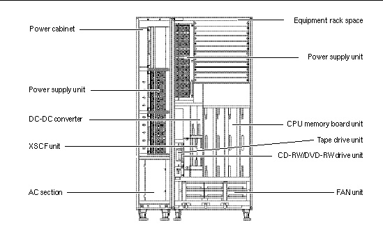
FIGURE 1-5 M8000 Server and Power Cabinet Rear View

FIGURE 1-6 and FIGURE 1-7 show the front and rear views of the M9000 server (base cabinet only) with a power cabinet connected. The names of server components are shown in each figure.
One power cabinet is connected to the M9000 server (base cabinet only).
FIGURE 1-6 M9000 Server (Base Cabinet Only) and Power Cabinet Front View
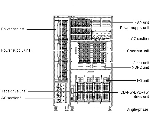
FIGURE 1-7 M9000 Server (Base Cabinet Only) and Power Cabinet Rear View
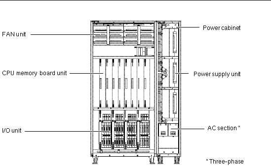
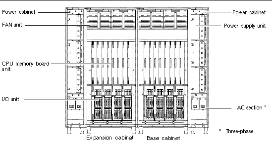
FIGURE 1-8 and FIGURE 1-9 show the front and rear views of the M9000 server with an expansion cabinet and power cabinets connected. The names of server components are shown in each figure.
One power cabinet is connected to each of M9000 server base cabinet and expansion cabinet.
FIGURE 1-8 M9000 Server (With an Expansion Cabinet) and Power Cabinet Front View
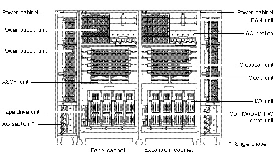
FIGURE 1-9 M9000 Server (With an Expansion Cabinet) and Power Cabinet Rear View
The operator panel has LEDs indicating different states of the M8000 and M9000 servers, a power switch for power control, and a mode switch for setting the operation mode.
The operator panel is mounted on the front panel.
For details about the operator panel, see the SPARC Enterprise M8000/M9000 Servers Service Manual.
The following figure shows the operator panel, and its LEDs and switches are described below.
FIGURE 1-10 shows the operator panel.
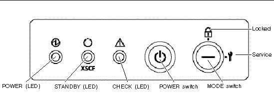
TABLE 1-4 lists the operating states indicated by the LEDs on the operator panel.
The switches on the operator panel include the mode switch for setting the operation mode and the POWER switch for turning on and off the server. To switch between system operation mode and maintenance mode, insert the dedicated key of the high-end server and change the mode switch setting.
TABLE 1-5 lists functions of the switches on the operator panel.
|
|
||||
|
|
|
|||
|
|
||||
|
|
||||
This section describes the components of both high-end servers.
For details on each, see the SPARC Enterprise M8000/M9000 Servers Service Manual.
The CPU module (CPUM) contains a SPARC64 VI/SPARC64 VII/SPARC64 VII+ processor and a DC-DC converter (DDC). Up to four CPUMs can be mounted on a CPU/memory board unit.
The CPUM has the following features:
The CPU/memory board unit (CMU) contains CPUMs, memory modules, and a DDC. The CMU with an I/O unit can be combined to construct one or more domains.
The CMU has the following features:
The I/O unit (IOU) consists of a PCIe bridge control LSI module, a printed circuit board containing a DDC, a hard disk drive (HDD), PCIe slots, and PCI cassettes for the IOU. The IOU and the CMU can be combined to configure domains.
The IOU has the following features:
The FAN unit is used to cool the server, and has the following features:
The power supply unit (PSU) feeds power to each unit, and has the following features:
The crossbar unit (XBU) consists of crossbar switches that logically connect CMUs and IOUs.
The XBU has redundant bus routes. If one route fails, the system can be restarted through the other route to continue operation.
The clock control unit (CLKU) contains an LSI module used for the clock.
The CLKU has redundant clock supply routes. If one route fails, the system can be restarted through the other route to continue operation.
The operator panel can be used to turn on and off the server power, switch between operation modes, and display system status information.
The operations of switches on the operator panel can be limited by switching the operation mode with the dedicated key supplied for the panel.
The XSCF unit (XSCFU) includes a dedicated processor, which operates independently from the main unit processors. The XSCFU in the servers adopts a duplicated configuration to increase fault tolerance.
The XSCFU is equipped with hardware interfaces for network connections to remote devices such as personal computers and workstations. A remote device can be connected via a network to the XSCF to control startup, settings, and operation management of the system.
The XSCFU provides the following hardware interfaces for network connections:
The XSCF can be accessed through network connections using these interfaces. The command line-based interface (XSCF Shell) and browser-based user interface (XSCF Web) provided by the XSCF enable operation and management of the servers.
For details, see the SPARC Enterprise M3000/M4000/M5000/M8000/M9000 Servers XSCF User’s Guide.
The M8000/M9000 servers contain the following in-cabinet drive units. These allow active replacement or addition.
The hard disk drive is a 2.5-inch hard disk drive with a serial attached SCSI (SAS) interface. It can be mounted in an IOU.
There are two types of CD-RW/DVD-RW drive units: slot-loading type and tray-loading type.
FIGURE 1-11 Types of CD-RW/DVD-RW Drive Unit
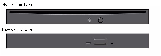
| Note - The locations of LED and button may vary depending on the servers. |
The CD-RW/DVD-RW drive unit cannot be directly shared by multiple domains in a server. However, if the multiple domains are connected to one another through a LAN and a certain function of the Oracle Solaris OS is used, the CD-RW/DVD-RW drive unit can be shared by the domains. Adequate consideration of security is necessary for LAN connections between domains.
Contact your sales representative for tape drive unit options on M8000/M9000 servers.
This section describes the component mounting conditions.
The following products are the main options available for the M8000/M9000 servers.
The power cabinet and the rack-mountable dual power feed option for the M8000 server are offered as power supply options.
The power cabinet enables dual power feed or three-phase power feed.
The rack-mountable dual power feed option for the M8000 server receives power from two external AC power sources that are independent of each other, and duplicates the input power system.
To use a single-phase dual power feed configuration for the M8000 server, mount the rack-mountable dual power feed option in the rack space itself. This requires a rack space with a height of 6 RUs in the cabinet. For the M9000 server, you must add the power cabinet.
For three-phase power feed in either server, an additional power cabinet is required. Install one power cabinet for each M8000/M9000 server.
For details, see the SPARC Enterprise M8000/M9000 Servers Site Planning Guide.
TABLE 1-6 lists specifications of the power cabinet.
| Note - For specifications of the three-phase power feed option, see the SPARC Enterprise M8000/M9000 Servers Site Planning Guide. |
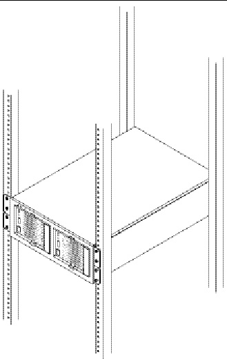
The External I/O Expansion Unit is an optional product used to add PCI slots. The External I/O Expansion Unit has a height of four RUs (rack units), about 18 cm, in an equipment rack.
The External I/O Expansion Unit can accommodate up to two I/O boats by using either six PCIe slots or six PCI-X slots.
Also, active addition and replacement is enabled for all slots in the External I/O Expansion Unit.
For details, see the External I/O Expansion Unit Installation and Service Manual.
FIGURE 1-12 External I/O Expansion Unit
An M9000 server (base cabinet) configuration can contain up to 32 CPU modules (64 cores for SPARC64 VI processors, 128 cores for SPARC64 VII/SPARC64 VII+ processors), up to 2 TB of memory, and up to 224 PCI slots. A configuration containing more components than described above would require the expansion cabinet option of the M9000 server.
A configuration with the M9000 server (expansion cabinet) can contain up to 64 CPU modules (128 cores for SPARC64 VI processors, 256 cores for SPARC64 VII/SPARC64 VII+ processors), up to 4 TB of memory, and up to 288 PCI slots.
For information about connecting the M9000 server (expansion cabinet) and the M9000 server (base cabinet), see the SPARC Enterprise M8000/M9000 Servers Installation Guide.
The M8000/M9000 servers use XSCF for system administration and monitoring.
The Oracle Solaris OS can be installed as the operating environment used in a domain.
For details, see Chapter 3.
| SPARC Enterprise M8000/M9000 Servers Overview Guide | 819-4204-15 |
Copyright © 2007, 2010, FUJITSU LIMITED. All rights reserved. Oracle and/or its affiliates provided technical input and review on portions of this material.


