C H A P T E R  2

Information About Hardware

This section describes the special instructions and the issues about the SPARC Enterprise M8000/M9000 server hardware.


Hardware Issues and Workarounds

Booting Multiple Systems From a Single J4200 JBOD Storage Array

Sun Storage J4200 SAS JBOD arrays have six general-purpose SAS connectors. With FW version 3A32 or higher, each of them can be connected to separate SAS initiators, therefore up to six systems can be connected to the array. Each system can use a different disk on the array as its boot device. J4200 arrays have 12 disks, so each boot device can be mirrored for higher reliability. J4200 arrays can be configured into multiple zones to provide a more secure environment.

For related information, see Sun StorageTek Common Array Manager Software documentation, at:
http://docs.sun.com/app/docs/prod/stor.arrmgr#hic

See especially:

DVD Drives and cfgadm

The Solaris cfgadm(1M) command does not always unconfigure a DVD drive from a domain on SPARC Enterprise M8000/M9000 servers.

Disable the Volume Management Daemon (vold) before unconfiguring a DVD drive with the cfgadm(1M) command. To disable vold, stop the daemon by issuing the command /etc/init.d/volmgt stop. After the device has been removed or inserted, restart the daemon by issuing the command /etc/init.d/volmgt start.

Sun Crypto Accelerator 6000 Cards

If you are not using the correct version of the Sun Crypto Accelerator (SCA) 6000 card driver, hot-plug operations on SCA 6000 cards can cause SPARC Enterprise M8000/M9000 servers to panic or hang. Version 1.1 of the SCA6000 driver and firmware supports hot-plug operations after the required bootstrap firmware upgrade has been performed. Version 1.0 of the SCA6000 driver does not support hot-plug and should not be used.

U320 PCIe SCSI Card

U320 PCIe SCSI card, part numbers 375-3357-01/02, is not supported in PCI cassettes for Sun SPARC Enterprise M8000/M9000 servers. Customers must use part number 375-3357-03 at a minimum.


Hardware Documentation Updates

This section contains important and late-breaking hardware information and corrections that became known after the documentation set was published.


TABLE 2-1 Hardware Documentation Updates

Title

Section Number

Update

SPARC Enterprise M8000/M90000 Servers Service Manual


Section 6.5

Section 7.2

The section, “Antistatic Precautions” will be added to the following Chapters;

  • Chapter 6: Replacement of CPU/Memory Board Unit (CMU), CPU, and DIMM
  • Chapter 7: I/O Unit (IOU) Replacement

See Antistatic Precautions.


SPARC Enterprise M8000/M90000 Servers Site Planning Guide


Section 1.2.1.2

TABLE 1-3 “External Dimensions and Weights"

The footnote regarding weight will be updated. See External Dimensions and Weights.


Section 3.2.1

“Cooling (Air Conditioning) Requirements"

The Specifications (Cooling and Air-Conditioning Requirements) table will be updated. See Cooling (Air-Conditioning) Requirements.


Section 3.3

The values of power consumption and apparent power will be corrected in the following tables:

  • TABLE 3-5 "Specifications (Single-Phase Power Requirements),"
  • TABLE 3-7 "Specifications (Three-Phase Delta Power Requirements),"
  • TABLE 3-8 "Specifications (Three-Phase Star Power Requirements)"

See Electrical Specifications


Section 3.3.6

“CPU Types and Server Maximum Power Consumption”

The CPU Types and Server Maximum Power Consumption information will be updated. See CPU Types and Server Maximum Power Consumption.

SPARC Enterprise M8000/M90000 Servers Overview Guide

Section 1.2.2

TABLE 1-3 “Power Consumption Examples”

The Power Consumption Examples table will be updated. See Electrical Specifications.


Ambient Environmental Requirements

The table found in Section 2.2.1 of the Sun SPARC Enterprise M8000/M9000 Servers Overview Guide will be updated with the information in TABLE 2-2, below.


TABLE 2-2 Ambient Environmental Requirements

Operating Range

Non-Operating Range

Optimum

Ambient

temperature

5˚C to 32˚C

(41˚F to 89.6˚F)

Unpacked:

0˚C to 50˚C (32˚F to 122˚F)

Packed:

-20˚C to 60˚C (-4˚F to 140˚F)


21˚C to 23˚C

(70˚F to 74˚F)

Relative

humidity[1]

20% RH to 80% RH

to 93% RH

45% RH to 50% RH


Altitude

restriction[2]

3,000 m (10,000 ft)

12,000 m (40, 000 ft)


Temperature

conditions

5˚C to 32˚C (41˚F to 89.6˚F) at an installation altitude ranging from 0 to less than 1500 m (4921 feet) above sea level


5˚C to 30˚C (41˚F to 86˚F) at an installation altitude ranging from 1500 m (4921 feet) to less than 2000 m (6562 feet) above sea level


5˚C to 28˚C (41˚F to 82.4˚F) at an installation altitude ranging from 2000 m (6562 feet) to less than 2500 m (8202 feet) above sea level


5˚C to 26˚C (41˚F to 78.8˚F) at an installation altitude ranging from 2500 m (8202 feet) to 3000 m (9843 feet) above sea level


Antistatic Precautions


caution icon Caution - Before handling FRUs, be sure to connect an antistatic wrist strap clip and an antistatic conductive mat to a cabinet grounding port and attach the band of the wrist strap to one of your wrists. Remove static electricity on the FRUs before installation by placing the FRUs on a grounded antistatic conductive mat while wearing the wrist strap. Failure to do so might result in serious damage.


Be sure to observe the precautions when handling the FRUs described in the below chapters in the SPARC Enterprise M8000/M9000 Servers Service Manual.


caution icon Caution - Do not touch the CMU, IOU, or the dummy unit without wearing an antistatic wrist strap. Failure to do so might result in serious damage to operating domains.


Method of Removing Static Electricity

This section provides the information on the method of removing static electricity.

1. Connect an antistatic conductive mat to a server grounding port. See Grounding Port Connection Locations.


Note - Do not use antistatic bags or packaging materials in place of a grounded antistatic conductive mat when handling the FRUs.


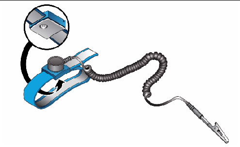
2. Connect an antistatic wrist strap clip to a server grounding port. See Grounding Port Connection Locations.

3. Ensure that the metallic underside of the wrist strap is in direct contact with your skin.

The wrist strap should be snug around the wrist so that it does not rotate.


FIGURE 2-1 Antistatic Wrist Strap Showing the Metallic Underside


4. To mount a FRU, place it on the grounded antistatic conductive mat. With your bare hand wearing the antistatic wrist strap, touch the metallic FRU chassis for 5 or more seconds.

When touching the FRU, take care not to damage the parts such as the connector on the edge of the unit.


caution icon Caution - Do not touch the CMU, IOU, or the dummy unit without wearing an antistatic wrist strap. Failure to do so might result in serious damage to operating domains.


Removing Static Electricity on a CMU and an IOU

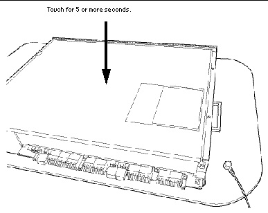
a. Prior to mounting a new CMU or IOU, place it on the grounded antistatic conductive mat.

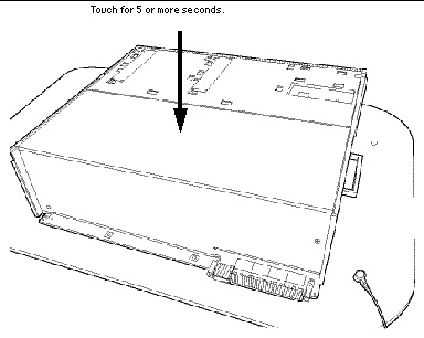
b. Touch the metallic chassis for 5 or more seconds with your bare hand wearing the antistatic wrist strap. (See FIGURE 2-2 or FIGURE 2-3)

You cannot remove static electricity by touching the label.

FIGURE 2-2 Metallic Chassis (CMU)


 [ D ]

FIGURE 2-3 Metallic Chassis (IOU)


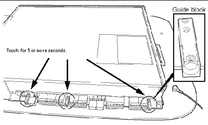
c. Touch each of the designated points on the guide blocks for 5 or more seconds with your bare hand wearing the antistatic wrist strap. (See FIGURE 2-4 or FIGURE 2-5)

FIGURE 2-4 Guide Blocks (CMU)


FIGURE 2-5 Guide Blocks (IOU)


Grounding Port Connection Locations

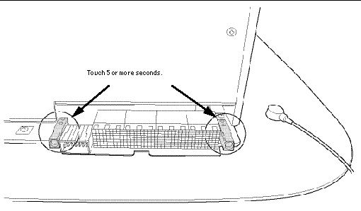
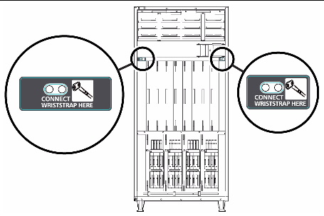
This section provides the information of the grounding port connection locations of the M8000/M9000 servers.

The grounding port can be used to connect the clip of the antistatic wrist strap and the antistatic conductive mat.

FIGURE 2-6 M8000 Grounding Port Connection Locations for the Wrist Strap Clip and the Antistatic Conductive Mat (Front View)


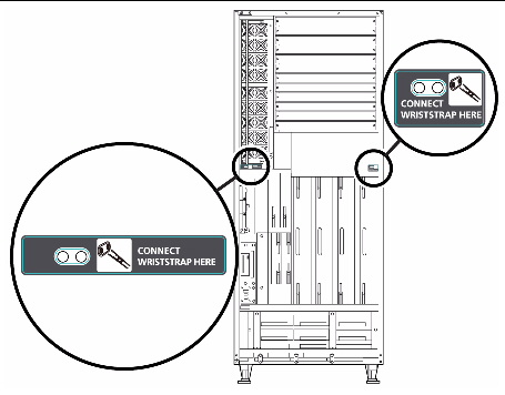
FIGURE 2-7 M8000 Grounding Port Connection Locations for the Wrist Strap Clip and the Antistatic Conductive Mat (Rear View)


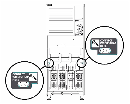
FIGURE 2-8 M9000 Grounding Port Connection Locations for the Wrist Strap Clip and the Antistatic Conductive Mat (Front View)


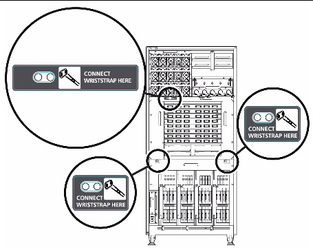
FIGURE 2-9 M9000 Grounding Port Connection Locations for the Wrist Strap Clip and the Antistatic Conductive Mat (Rear View)


External Dimensions and Weights

The table found in Section 1.2.1.2 of the Sun SPARC Enterprise M8000/M9000 Servers Site Planning Guide will be updated with the information in TABLE 2-3, below. The table lists the external dimensions and weights of the Sun SPARC Enterprise M8000/M9000 server cabinet.


TABLE 2-3 Installation Specifications (External Dimensions and Weights)

Name

External dimensions [mm (inch)]

Weight [kg]

Width

Depth

Height

SPARC Enterprise M8000 server

750 (29.5)

1260 (49.6)

1800 (70.9)

700[3]

M8000 + Power Cabinet

1054 (41.5)

1260 (49.6)

1800 (70.9)

1020

SPARC Enterprise M9000 server (base cabinet)

850 (33.5)

1260 (49.6)

1800 (70.9)

940

M9000 (base cabinet) + Power Cabinet

1154 (45.4)

1260 (49.6)

1800 (70.9)

1290

M9000 (base cabinet + expansion cabinet)

1674 (65.9)

1260 (49.6)

1800 (70.9)

1880[4]

M9000 (base cabinet + expansion cabinet) + Power Cabinet

2282 (89.8)

1260 (49.6)

1800 (70.9)

2580

Rack-mountable Dual Power Feed

489 (19.3)

1003 (39.5)

278 (10.9)

[6U]

75[5]

Power Cabinet

317 (12.5)

1244 (49.0)

1800 (70.9)

350[6]


Cooling (Air-Conditioning) Requirements

The Specifications (Cooling and Air-Conditioning Requirements) table found in Section 3.2.1 of the Sun SPARC Enterprise M8000/M9000 Servers Site Planning Guide will be updated with the information in TABLE 2-4, below. The table lists the cooling and air-conditioning requirements for each system component.


TABLE 2-4 Specifications (Cooling and Air-Conditioning Requirements)

Name

Heat dissipation [kJ/h]

Exhaust airflow [cmh(m3/h)]

Cooling method

Air-conditioning type

Noise level [dBA]

SPARC Enterprise M8000 server

13968-37764 [7]

94

Overfloor/underfloor

Forced air cooling

67

SPARC Enterprise M9000 server (base cabinet)

22320-71532 *

102

Overfloor/underfloor

Forced air cooling

68

SPARC Enterprise M9000 server (base cabinet + expansion cabinet)

42912-142956 *

205

Underfloor

Forced air cooling

69

Rack-mountable Dual Power Feed

- [8]

-

Overfloor/underfloor

Forced air cooling

-

Power Cabinet (SPARC Enterprise M8000 server)

-

-

Overfloor/underfloor

Forced air cooling

-

Power Cabinet (for SPARC Enterprise M9000 server base cabinet)

-

-

Overfloor/underfloor

Forced air cooling

-

Power Cabinet (for SPARC Enterprise M9000 server base cabinet + expansion cabinet)


-

-

Underfloor

Forced air cooling

-


Electrical Specifications

Section 3.3 of the Sun SPARC Enterprise M8000/M9000 Servers Site Planning Guide will be updated with the following tables.


TABLE 2-5 Specifications [9] (Single-Phase Power Requirements)

NAME

Power consumption [kW]

Apparent power [kVA]

SPARC Enterprise M8000 server

3.88-10.49

4.11-11.12

SPARC Enterprise M9000 server (base cabinet)

6.20-19.87

6.58-21.07

SPARC Enterprise M9000 server

(base cabinet + expansion cabinet)

11.92-39.72

12.64-42.13


TABLE 2-6 Specifications [10] (Three-Phase Delta Power Requirements)

NAME

Power consumption [kW]

Apparent power [kVA]

SPARC Enterprise M8000 server + Power Cabinet

3.88-10.49

4.11-11.12

SPARC Enterprise M9000 server

(base cabinet) + Power Cabinet

6.20-19.87

6.58-21.07

SPARC Enterprise 9000 server

(base cabinet + expansion cabinet) + Power Cabinet

11.92-39.72

12.64-42.13


TABLE 2-7 Specifications [11] (Three-Phase Star Power Requirements)

NAME

Power consumption [kW]

Apparent power [kVA]

SPARC Enterprise M8000 server + Power Cabinet

3.88-10.49

4.11-11.12

SPARC Enterprise M9000 server

(base cabinet) + Power Cabinet

6.20-19.87

6.58-21.07

SPARC Enterprise 9000 server

(base cabinet + expansion cabinet) + Power Cabinet

11.92-39.72

12.64-42.13


CPU Types and Server Maximum Power Consumption

The CPU Types and Power Specifications information found in Section 3.3.6 of the Sun SPARC Enterprise M8000/M9000 Servers Site Planning Guide will be updated with the information that appears below, including the following tables.

This section describes the CPU types and the maximum power consumption of the server. There are four types of CPU. The power specifications of the SPARC Enterprise M8000/M9000 servers vary depending on the CPU type and the system configurations.

The tables list the specifications of maximum power consumption, apparent power, and heat dissipation by the type of CPU. The figures represent the system configuration described below the table, in which every CPU/Memory Board Unit (CMU) is mounted with the same CPU.


TABLE 2-8 CPU Types and Power Specifications on the M8000 Server [12]

CPU

Frequency (GHz)

Number

Power Consumption (KW)

Apparent Power (KVA)

Heat dissipation (KJ/h)

SPARC64 VI processor

2.28

16

9.42

9.99

33912

2.4

16

9.52

10.09

34272

SPARC64 VII processor

2.52

16

10.07

10.68

36252

2.88

16

10.49

11.12

37764


TABLE 2-9 CPU Types and Power Specifications on the M9000 Server (Base Cabinet) [13]

CPU

Frequency (GHz)

Number

Power Consumption (KW)

Apparent Power (KVA)

Heat dissipation (KJ/h)

SPARC64 VI processor

2.28

32

18.06

19.16

65016

2.4

32

18.26

19.37

65736

SPARC64 VII processor

2.52

32

19.36

20.54

69696

2.88

32

19.87

21.07

71532


TABLE 2-10 CPU Types and Power Specifications on the M9000 Server (Base Cabinet + Expansion Cabinet) [14]

CPU

Frequency (GHz)

Number

Power Consumption (KW)

Apparent Power (KVA)

Heat dissipation (KJ/h)

SPARC64 VI processor

2.28

64

36.11

38.30

129996

2.4

64

36.51

38.73

131436

SPARC64 VII processor

2.52

64

38.71

41.06

139356

2.88

64

39.72

42.13

142992


Electrical Specifications

Section 1.2.2 of the Sun SPARC Enterprise M8000/M9000 Servers Overview Guide will be updated with the information that appears below, including the following tables. The table shows samples of power consumption of specific configurations and program load. The power consumption of the system varies depending on configuration of the system, characteristics of your running programs and ambient temperature.


TABLE 2-11 Power consumption Examples

Item

M8000

M9000


Base cabinet only

Base cabinet + expansion cabinet

Ambient temperature

25 ˚C

25 ˚C

25 ˚C

Configuration[15]

CMU:

2.52GHz CPU x 4, 4GB DIMM x 32

4

8

16

IOU:

73GB HDD x 4, PCIe card x 8

4

8

16

Power consumption[16]

7.48 kW

14.64 kW

29.96 kW


1 (TableFootnote) There is no condensation regardless of the temperature and humidity.
2 (TableFootnote) All altitudes are above sea level.
3 (TableFootnote) The weights listed in this table show a fully populated server: all CMU, IOU, PCI and DIMM slots are mounted. The weights do not include the weight of any optional hardware, such as the External I/O Expansion Unit
4 (TableFootnote) When combining a base cabinet and an expansion cabinet, the width of each cabinet is 837 mm (including the exterior side panels).
5 (TableFootnote) The Rack-mountable Dual Power Feed can only be mounted on the equipment rack.
6 (TableFootnote) The width of a Power Cabinet includes the exterior side panel. 
7 (TableFootnote) Heat dissipation varies by power consumption. Determine the power consumption based on the actual system configuration and then confirm the right value.
8 (TableFootnote) The heat dissipation, exhaust airflow and acoustic noise value of the Power Cabinet is included in the value for the SPARC Enterprise M8000 server or SPARC Enterprise M9000 server.‡ At an installation altitude ranging from 0 to less than 400 m (1312 feet) above sea level, you can select overfloor cooling as the cooling method of the server.


9 (TableFootnote) The values for maximum power consumption and apparent power vary by the type of CPU mounted. To plan the installation of a server equipped with different types of CPU, use the CPU of larger power consumption as a basis. For the types of CPU, see Section 3.3.6, "CPU Types and Server Maximum Power Consumption"of the Sun SPARC Enterprise M8000/M9000 Servers Site Planning Guide.
10 (TableFootnote) The values for maximum power consumption and apparent power vary by the type of CPU mounted. To plan the installation of a server equipped with different types of CPU, use the CPU of larger power consumption as a basis. For the types of CPU, see Section 3.3.6, "CPU Types and Server Maximum Power Consumption" of the Sun SPARC Enterprise M8000/M9000 Servers Site Planning Guide..
11 (TableFootnote) The values for maximum power consumption and apparent power vary by the type of CPU mounted. To plan the installation of a server equipped with different types of CPU, use the CPU of larger power consumption as a basis. For the types of CPU, see Section 3.3.6, "CPU Types and Server Maximum Power Consumption" of the Sun SPARC Enterprise M8000/M9000 Servers Site Planning Guide..
12 (TableFootnote) The M8000 system configuration: CMU x 4, 4GB DIMM x 128, IOU x 4, HDD x 16, PCI-E x 32, DAT x1.
13 (TableFootnote) The M9000 (base cabinet) system configuration: CMU x 4, 4GB DIMM x 128, IOU x 4, HDD x 16, PCI-E x 32, DAT x1.
14 (TableFootnote) The M9000 (base cabinet + expansion cabinet) system configuration: CMU x 16, 4GB DIMM x 512, IOU x 16, HDD x 64, PCI-E x 128, DAT x2.
15 (TableFootnote) 10Watt PCIe cards are installed.
16 (TableFootnote) These power consumptions are just samples. You can see higher power consumption values depending on characteristics of your workload.