| C H A P T E R 4 |
|
Specifications, Components, and Connectors |
This chapter contains information on the specifications, components, and connectors for the Sun Netra CP32x0 ARTM-FC.
This chapter contains the following sections:
This section provides mechanical, electrical, environmental, and other relevant specifications for the Sun Netra CP32x0 ARTM-FC.
The Sun Netra CP32x0 ARTM-FC is a 6U (322.25 mm) height board with 81 mm in depth for standard applications. It complies with IEEE 1101.11 mechanical standards, as required by the PICMG 2.0 Revision 3.0 specification. The Sun Netra CP32x0 ARTM-FC is keyed to conform to the PICMG 2.10, Keying of ATCA Boards and Backplane specification.
The power consumption of the ARTM-FC card is limited to 25 W maximum. The
3.3 V management power is limited to 150 mA and the current limit set point for the 12 V payload power is 2.5 A.
The Sun Netra CP32x0 ARTM-FC is powered through the Netra ATCA node board. The node board provides the following voltages: 3.3 V and 12 V.
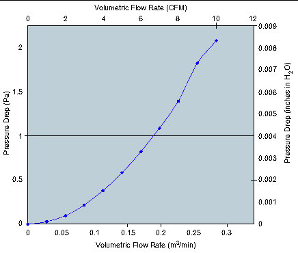
TABLE 4-1 shows the Sun Netra CP32x0 ARTM-FC airflow requirements. TABLE 4-2 and FIGURE 4-1 show the worst-case pressure drop as a function of air flow rate.

The environmental specifications for the Sun Netra CP32x0 ARTM-FC assembly are as follows.
The Sun Netra CP32x0 ARTM-FC maximizes communications input/output (I/O) for GbE networks by providing four fixed 10BASE-T, 100BASE-TX, or 1000BASE-T ports and two modular SFP ports, controlled by a device on the ATCA blade, on a single module.
The Sun Netra CP32x0 ARTM-FC contains the following components and connectors. See FIGURE 4-2 for a block diagram and Section 4.3, Connectors and Pin Assignments.
The Sun Netra CP32x0 ARTM-FC contains a x8 PCI-E connection that complies with the AMC.1 specification. This PCI-E is switched into four x4 ports: one to each of the two Ethernet controllers, one to a x4 PCI-E cable connector, and one to the Fibre Channel controller. The onboard Emulex IOC3532 controller supports two Fibre Channel ports with fabric switching for high speed and high capacity storage access. The two onboard Intel 82571EB controllers support four fixed GbE copper ports. The other two GbE ports are supported by the Ethernet controller on the host board using a SERDES protocol.
The RS-232 serial port and the LAN Management port are used for managing the host ATCA blade.
The Sun Netra CP32x0 ARTM-FC provides one 10/100/1000BASE-T Ethernet management port as an RJ-45 connector equipped with LEDs.
The Sun Netra CP32x0 ARTM-FC provides one asynchronous RJ-45 serial port as an
RJ-45 connector. The serial port may be redirected to and from the front node board when using an ARTM-FC-compatible node board. For more information on using both the front and rear serial ports, refer to the appropriate node board documentation.
The onboard MMC provides IPMI management communication between the
ARTM-FC and the node board, and local monitoring of temperature and voltage. The MMC also controls the Hot-swap function.
The Hot-swap latch allows for easy module replacement during live operation.
The Sun Netra CP32x0 ARTM-FC contains an IPMI FRU PROM compatible with the ATCA specification.
The PCI-Express Switch is used to aggregate the two Ethernet Controllers, Fibre Channel Controller, and external PCI-E cable connector into a x8 PCI-E port connected to the rear I/O of the ARTM-FC via the Zone 3 connectors. Each of these devices is connected by a x4 port to the PCI-Express Switch.
The Sun Netra CP32x0 ARTM-FC supports two Fibre Channel ports provided by the onboard Emulex IOC3532 controller. These ports connect to SFP modules. The controller supports Fibre Channel link speeds of 1, 2, and 4 Gbps. These rates are software-selectable, but may be limited by the capability of the module installed.
Firmware for the Fibre Channel controller, including x86 and SPARC© boot BIOS, is included and can be configured using Emulex utilities. The boot BIOS settings can be accessed during the boot sequence.
A network based on the 10BASE-T standard uses unshielded twisted-pair cables, providing an economical solution to the networking by allowing the use of existing telephone wiring and connectors. The RJ-45 connector is used with the 10BASE-T standard. 10BASE-T has a maximum length of 100 meters.
The Sun Netra CP32x0 ARTM-FC also supports the 100BASE-TX Ethernet. A network based on a 100BASE-TX standard uses unshielded twisted-pair cables and an RJ-45 connector. 100BASE-TX has a maximum length of 100 meters.
The Sun Netra CP32x0 ARTM-FC supports GbE offering speeds of 1000 Mbps. It is fully compatible with existing Ethernet, as it uses the same CSMA/CD and MAC protocols. 1000BASE-T has a maximum length of 3000 meters using Single-mode fiber-optic cables.
Each dual GbE controller supports two fixed GbE ports via copper RJ-45 connectors. The controllers support 10BASE-T, 100BASE-TX, and 1000BASE-T operational modes, which comply with IEEE 802.3 (802.3u, 802.3ab) specifications, and TCP segmentation and checksum offloading, reducing the host CPU utilization. Each port features auto-negotiations and automatic MDI/MDIX switchover on RJ-45 ports to enable greater compatibility with existing devices and infrastructures. Both full duplex and half-duplex modes are supported in 10BASE-T and 100BASE-TX modes. The 1000BASE-T mode supports only full-duplex operations.
Each dual GbE controller supports boot over LAN using a PXE boot ROM, which can be configured during the boot sequence. This firmware appears to the protocol stack as ordinary MAC layer interfaces and is ready to use without modifications. The protocol stack simply interfaces to a MAC-layer driver, which communicates to the onboard GbE MACs through the PCI-Express bus.
The Sun Netra CP32x0 ARTM-FC supports two GbE ports connected directly to the Ethernet controller on the host board using a SERDES protocol. These ports connect to SFP modules. The module type (fiber or copper) is user-configurable.
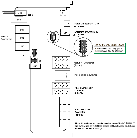
FIGURE 4-2 is an illustration of the Sun Netra CP32x0 ARTM-FC connectors, switches, and headers.
FIGURE 4-2 Sun Netra CP32x0 ARTM-FC Connectors

| Note - All switches and headers on the Sun Netra CP32x0 ARTM-FC are factory-use only. |
|
Guide Modules - for proper keying and alignment to the appropriate node board |
The Sun Netra CP32x0 ARTM-FC provides the following I/O connectors.
FIGURE 4-3 illustrates the connectors for the LAN and Serial Management. TABLE 4-5 shows the pin assignments for the LAN connector and TABLE 4-6 shows the pin assignments for the serial connector.
FIGURE 4-3 LAN and Serial Management Connectors (J35 and J34)

| Note - All four ports have the same pinouts. |
This connector provides two ports supporting modules for either copper cable or optical fiber. The ports can be either both copper or both optical, or one can be copper and the other optical. (The ports are independent of each other.)
FIGURE 4-4 GbE SPF Connector (J38)

This connector provides support for one external x4 PCI-E cable connection.
FIGURE 4-5 PCI-E Cable Connector (J40)

This connector provides two ports for Fibre Channel, using optical fiber only.
FIGURE 4-6 Fibre Channel SFP Connector (J37)

All four GbE RJ-45 copper ports are encompassed in this one connector (see FIGURE 4-7). They are arranged from bottom to top, labeled 1 through 4. (These ports are independent of each other.) TABLE 4-10 lists the basic signal names.
FIGURE 4-7 GbE RJ-45 Copper Connector (J36)

| Note - All four ports have the same pinouts. |
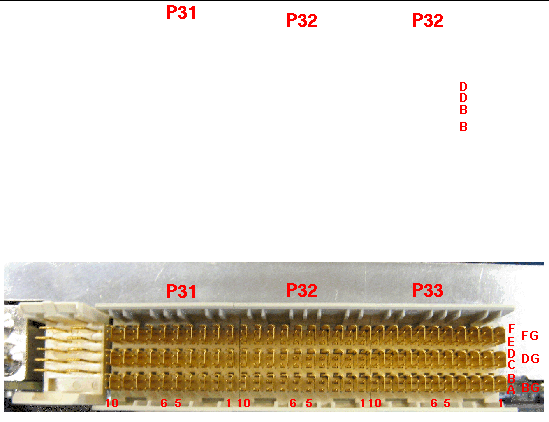
The I/O connections for rear access are provided by the Netra node board through the Zone 3 connectors. The Zone 3 I/O connectors are P31, P32, and P33. The Zone 3 connectors are shown in FIGURE 4-8. The pin assignments for P32 and P33 are in TABLE 4-11 and TABLE 4-12. P31 is not used on the Sun Netra CP32x0 ARTM-FC.
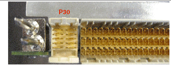
P30 (Power/Management connector) is also part of Zone 3. See FIGURE 4-9 and TABLE 4-13 for the illustration and pin assignments.
FIGURE 4-8 Backplane Connectors for Zone 3

| Note - N/C indicates No Connection |
FIGURE 4-9 Power/Management Connector (P30) for Zone 3

Copyright © 2009 Sun Microsystems, Inc. All rights reserved.