|
|
| Sun ONE Directory Server 5.2 Deployment Guide |
Chapter 10 Architectural Strategies
There are several factors to take into consideration when planning your directory deployment. Some of the most important considerations include the physical location of your data, how and where this data is replicated, what you can do to minimize failures, and how to react when failures do occur. The architectural strategies outlined in this chapter provide you with some guidelines.
This chapter is divided into the following sections:
Addressing Failure and Recovery
It is essential to have a strategy in place for providing minimum disruption of service in the case of failure. For our purposes, failure is defined as anything that prevents Directory Server from providing the minimum level of service you require. This section describes the various reasons for which failure can occur, which will assist you in identifying and managing failures in your deployment.
Failure can be divided into two main areas:
- System unavailable
- System unreliable
The system may be unavailable due to any of the following:
- Network problem - the network may be down, slow or intermittent.
- Process (slapd) problem - the process may be down, busy, restarting, or unwilling to perform.
- Hardware problem - the hardware may be off, may have failed, or may be rebooting.
The system may be unreliable due to any of the following:
- Replication failure or latency, causing data to be out of date or unsynchronized.
- System too busy - an excess of read or write operations may result in unreliable data.
To maintain the ability to add and modify data in the directory, write operations should be routed to an alternative server in the event of a writable server becoming unavailable. Various methods can be used to reroute write operations, including the Sun ONE Directory Proxy Server.
To maintain the ability to read data in the directory, a suitable load balancing strategy must be put in place. Both software and hardware load balancing solutions exist to distribute read load across multiple consumer replicas. Each of these solutions also has the capability (to varying degrees of completeness and accuracy) to determine the state of each replica and to manage its participation in the load balancing topology.
Replicating directory contents increases the availability and performance of Directory Server. A reliable replication topology will ensure that the most recent data is available to clients across data centers, even in the case of failure.
In the following sections, failure strategies for read and write operations are discussed as they relate to each replication topology.
Planning a Backup Strategy
In any failure situation involving data corruption or data loss, it is imperative that you have a recent backup of your data. If you do not have a recent backup, you will be required to re-initialize a failed master from another master. For a comprehensive set of procedures on how to back up your data, refer to Backing Up Data in the Sun ONE Directory Server Administration Guide.
This section provides a brief overview of what you should consider when planning a backup and recovery strategy.
Choosing a Backup Method
Sun ONE Directory Server provides two methods of backing up data: binary backup (db2bak) and backup to an ldif file (db2ldif). Both of these methods have advantages and limitations, and knowing how to use each method will assist you in planning an effective backup strategy.
Binary Backup (db2bak)
Binary backup is performed at the file system level. The output of a binary backup is a set of binary files containing all entries, indexes, the change log and the transaction log.
Note The dse.ldif configuration file is not backed up in a binary backup. You should back this file up manually to enable you to restore a previous configuration.
Performing a binary backup has the following advantages:
- All suffixes can be backed up at once.
- Binary backup is significantly faster than a backup to ldif.
Binary backup has the following limitations:
- Restoration from a binary backup can be performed only on a server with an identical configuration. This implies that:
- Both machines must use the same hardware and the same operating system, including any service packs or patches.
- Both machines must have the same version of Directory Server installed, including binary format (32 bits or 64 bits), service pack and patch level.
- Both servers must have the same directory tree divided into the same suffixes. The database files for all suffixes must be copied together, individual suffixes cannot be copied.
- Each suffix must have the same indexes configured on both servers, including VLV (virtual list view) indexes. The databases for the suffixes must have the same name.
- The Directory Server to be copied must not hold the o=NetscapeRoot suffix, which means it cannot be a configuration directory for the Sun ONE Administration Server.
- Each server must have the same suffixes configured as replicas, and replicas must have the same role (master, hub, or consumer) on both servers. If fractional replication is configured, it must be configured identically on all master servers.
- Attribute encryption must not be used on either server.
For more information on restoring data with the binary restore feature, refer to Initializing a Replica Using Binary Copy in the Sun ONE Directory Server Administration Guide.
At a minimum, you should perform a regular binary backup on each set of coherent machines (machines that have an identical configuration, as defined previously).
Note Because it is easier to restore from a local backup, it is recommended that you perform a binary backup on each server.
In all of the diagrams that follow in this chapter:
- M = master
- H = hub
- C = consumer
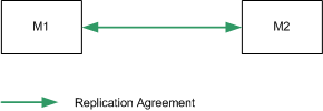
- RA = replication agreement.
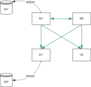
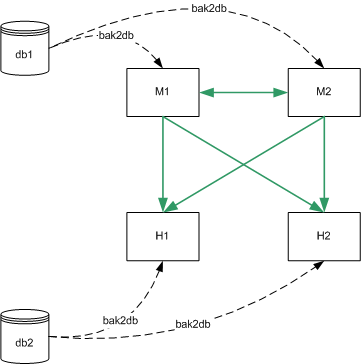
Figure 10-1 assumes that M1 and M2 have an identical configuration and that H1 and H2 have an identical configuration. In this scenario, a binary backup would be performed on M1 and on H1. In the case of failure, either master could be restored from the binary backup of M1 (db1) and either hub could be restored from the binary backup of H1 (db2). A master could not be restored from the binary backup of H1 and a hub could not be restored from the binary backup of M1.
Figure 10-1 Binary Backup
Backup to LDIF (db2ldif)
Backup to ldif is performed at the suffix level. The output of db2ldif is a formatted ldif file. As such, this process takes longer than a binary backup.
Backup to ldif has the following advantages:
- Backup to ldif can be performed from any server, regardless of its configuration.
- Restoration from a backup to ldif can be performed on any server, regardless of its configuration (if the -r option is used to export replication information.)
Backing up using backup to ldif has the following limitations:
- In situations where rapid backup and restoration are required, backup to ldif may take too long to be viable.
It is recommended that you perform a regular backup using backup to ldif for each replicated suffix, on a single master in your topology.
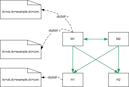
In the following diagram, db2ldif -r would be performed for each replicated suffix, on M1 only, or additionally on H1:
Figure 10-2 Backup Using db2ldif -r
Choosing a Restoration Method
Sun ONE Directory Server provides two methods of restoring data: binary restore (bak2db) and restoration from an ldif file (ldif2db). As with the backup methods discussed previously, both of these methods have advantages and limitations.
Binary Restore (bak2db)
Binary restore copies data at the database level. Restoring data using binary restore therefore has the following advantages:
- All suffixes can be restored at once.
- Binary restore is significantly faster than restoring from an ldif file.
Restoring data using binary restore has the following limitations:
- Restoration can be performed only on a server with an identical configuration, as defined on page 265. For more information on restoring data with the binary restore feature, refer to Initializing a Replica Using Binary Copy in the Sun ONE Directory Server Administration Guide.
- If you are unaware that your database was corrupt when you performed the binary backup, you risk restoring a corrupt database, since binary backup creates an exact copy of the database.
Binary restore is the recommended restoration method if the machines have an identical configuration, and time is a major consideration.
Figure 10-3 assumes that M1 and M2 have an identical configuration and that H1 and H2 have an identical configuration. In this scenario, either master can be restored from the binary backup of M1 (db1) and either hub can be restored from the binary backup of H1 (db2).
Figure 10-3 Binary Restore
Restoration From LDIF (ldif2db)
Restoration from an ldif file is performed at the suffix level. As such, this process takes longer than a binary restore. Restoration from an ldif file has the following advantages:
- It can be performed on any server, regardless of its configuration.
- A single ldif file can be used to deploy an entire directory service, regardless of its replication topology. This is particularly useful for the dynamic expansion and contraction of a directory service according to anticipated business needs.
Restoration from an ldif file has the following limitations:
- In situations where rapid restoration is required, ldif2db may take too long to be viable.
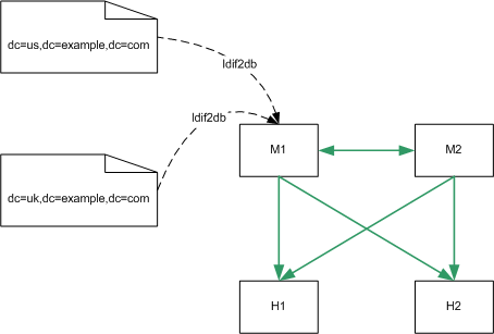
In the following diagram, ldif2db can be performed for each replicated suffix, on M1 only, or additionally on H1:
Figure 10-4 Restore Using ldif2db
Sample Replication Topologies
Your replication topology will be determined by the size of your enterprise and the physical location of your data centers. For this reason, we have provided sample replication topologies, categorized by the number of data centers (sites) in which the organization has a directory.
When you first deploy your directory, you will deploy according to the current number of entries and the current volume of reads/writes to the directory. As the number of entries increases, you will need to scale your directory for improved read performance. Suggestions for scalability are provided for each organization.
These topologies aim to provide continued service in the event of failure of one component, without immediate manual intervention. In the case of one and two data centers, local read/write failover is also provided.
Single Data Center
In a single data center, your topology is largely dependent on the anticipated performance requirements of the directory. In the basic topology suggested, it is assumed that the deployment warrants at least two servers to handle read and write operations. Two masters also provide a high-availability solution.
Single Data Center Basic Topology
The topology depicted in Figure 10-5 assumes one data center, with two masters for read and write performance. In this basic scenario, clients write to either master, and read from either master.
Figure 10-5 One Data Center - Basic Topology
Single Data Center Scaled For Read Performance
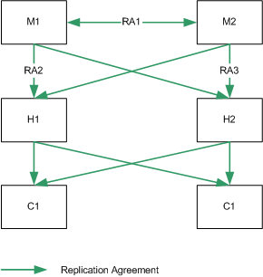
Increased read performance is achieved by adding hubs, and then consumers, as indicated in Figure 10-6. Hubs are added below the masters first to make adding a third level of consumers easier. Configuring the second level servers as hubs immediately will allow consumers to be added below them without having to reconfigure any of the machines.
Figure 10-6 One Data Center Scaled For Read Performance
Single Data Center Failure Matrix
In the scenario depicted in Figure 10-6, various components may be rendered unavailable for any one of the reasons described on page 264. These points of failure, and the related recovery actions are described in table Table 10-1.
Single Data Center Recovery Procedure (One Component)
In a single data center with two masters, read and write capability is maintained if one master fails. This section describes a sample recovery strategy that can be applied to reinstate the failed component.
The flowchart depicted in Figure 10-7, and the procedure that follows, assumes that one master (M1) has failed.
Figure 10-7 Single Data Center Recovery Sample Procedure (One Component)
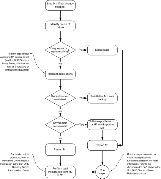
- Stop M1 (if it is not already stopped).
- Identify the cause of the failure. If it is easily repaired (by replacing a network cable, for example) make the repair.
- If the problem is more serious and will take time to fix, ensure that any applications accessing M1 are redirected to point to M2, via Sun ONE Directory Proxy Server, client server lists, or a hardware or software load balancer.
- If a recent backup is available, re-initialize M1 from the backup.
- If a recent backup is not available, restart M1 and perform a total initialization from M2 to M1. For details on this procedure, refer to Performing Online Replica Initialization in the Sun ONE Directory Server Administration Guide.
- If a recent backup is not available, and time considerations prevent you from performing a total initialization, perform an online export from H1, or H2, and an import (ldif2db) to M1.
- Start M1 (if it is not already started.)
- Set M1 to read/write mode (if it is in read-only mode.)
- Use the insync command to check that replication is now functioning correctly. For more information, refer to the documentation on "Insync" in the Sun ONE Directory Server Reference Manual.
Single Data Center Recovery Procedure (Two Components)
In the event of two masters failing in this scenario, write capability is lost. If the failure is serious and will take a long time to repair, it is necessary to implement a strategy that will provide write capability as rapidly as possible.
The following procedure assumes that both M1 and M2 have failed, and are unrecoverable in the near term. Note that you need to assess the quickest and least complicated method of recovery. This procedure depicts server promotion as the least complicated method, for illustration purposes.
- Promote H1 to a writable master. For information on how to do this, refer to "Promoting or Demoting Replicas" in the Sun ONE Directory Server Administration Guide.
- Ensure that any applications that were accessing either M1 or M2 are redirected to point to the new master.
- Add a replication agreement between the new master and H2 to ensure that modifications continue to be replicated to the consumers.
Two Data Centers
When data is shared across sites, an effective replication topology is imperative, for both performance and failover.
Two Data Centers Basic Topology
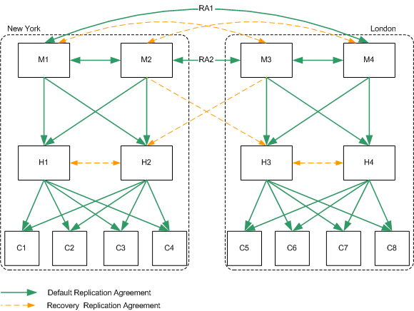
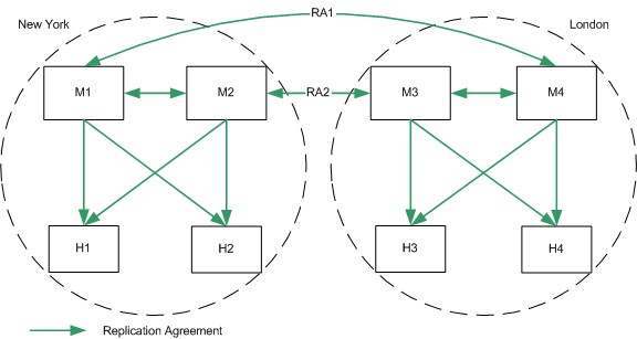
The topology depicted in Figure 10-8 assumes two masters and two hubs in each data center, for optimized read and write performance. Configuring the second level servers as hubs immediately will allow consumers to be added below them without having to reconfigure any of the machines.
In this scenario, it is recommended that the replication agreements RA1 and RA2 are configured over separate network links. This configuration will enable replication to continue across data centers, in the case of one of the network links becoming unavailable or unreliable.
Figure 10-8 Two Data Centers Basic Topology
Two Data Centers Scaled For Read Performance
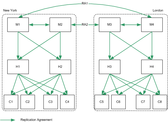
As in the scenario for one data center, increased read performance is achieved by adding hubs, and then consumers, as indicated in Figure 10-6.
In this scenario, it is recommended that the replication agreements RA1 and RA2 are configured over separate network links. This configuration will enable replication to continue across data centers, in the case of one of the network links becoming unavailable or unreliable.
Figure 10-9 Two Data Centers Scaled For Read Performance
Two Data Centers Recovery Scenarios
For the deployment depicted in Figure 10-9, if one master fails, the same recovery strategy can be applied as described for a single data center. The replication agreements between M1 and M4, and between M2 and M3, will ensure that both data centers continue to receive replicated updates, even if one of the masters in the data center is not available.
If more than one master fails, however, an advanced recovery strategy is required. This involves the creation of recovery replication agreements, that are disabled by default but can be enabled rapidly in the event of a failure.
This recovery strategy is illustrated in Figure 10-10.
Figure 10-10 Two Data Centers Recovery Replication Agreements
The recovery strategy applied will depend on which combination of components fails. However, once you have a basic strategy in place to cope with multiple failures, you can apply that strategy should other components fail.
In the sample topology depicted in Figure 10-10, assume that both masters in the New York data center fail. The recovery strategy in this scenario would be as follows:
- Enable the recovery replication agreement between M3 and H2.
This ensures that remote writes on the London site continue to be replicated to the New York site.
- Promote H2 to a writable master. For information on how to do this, refer to "Promoting or Demoting Replicas" in the Sun ONE Directory Server Administration Guide.
This ensures that write-capability is maintained on the New York site.
- Create a replication agreement between the new promoted master (was H2) and M3.
This ensures that writes on the New York site continue to be replicated to the London site.
- Enable the recovery replication agreement between H2 and H1 (one direction only.)
This ensures that H1 continues to receive updates from the entire replication topology.
Three Data Centers
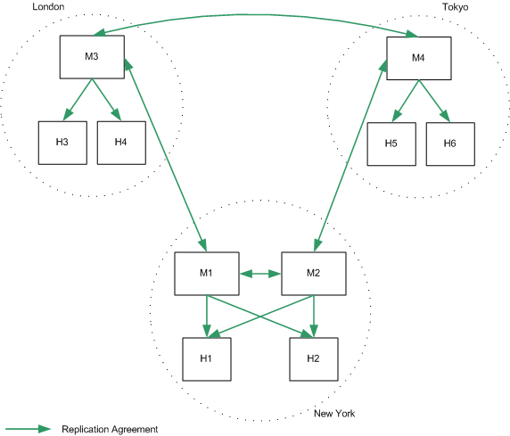
Directory Server 5.2 supports 4-way multi-master replication. In an enterprise spread over three main geographical regions, you have the possibility of two masters in one data center and one in each of the others. How you divide this directory capacity will be determined (amongst other issues) by the relative volume of read and write traffic anticipated in each data center.
Three Data Centers Basic Topology
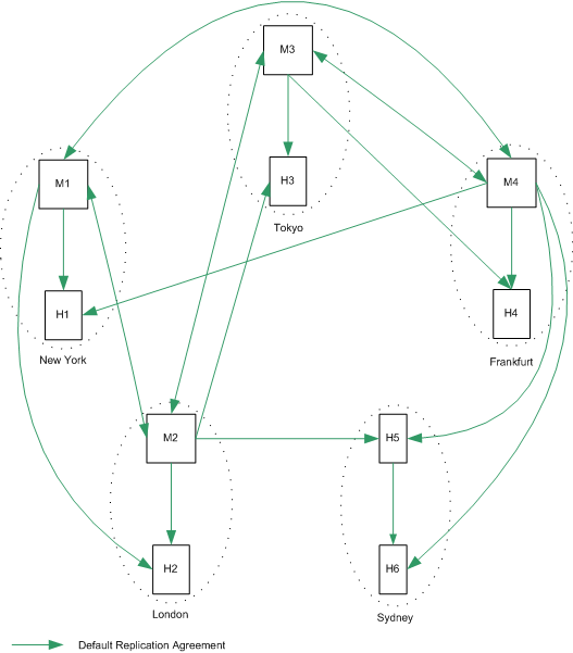
The topology depicted in Figure 10-11 assumes that the New York data center receives the largest number of read and write requests, although local read and write requests are possible in each of the three data centers.
Figure 10-11 Three Data Centers Basic Topology
Three Data Centers Scaled For Read Performance
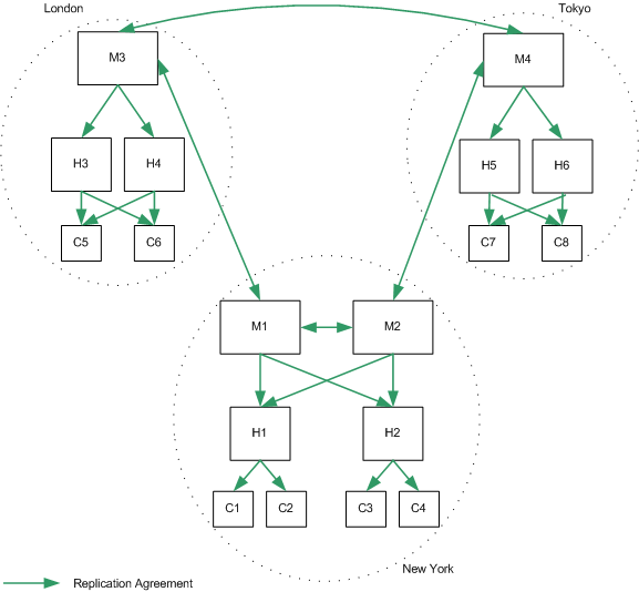
As in the previous scenarios, increased read performance is achieved by adding hubs and consumers, once again taking into account the anticipated performance requirements across the different data centers. The recommended topology is indicated in Figure 10-12.
Figure 10-12 Three Data Centers Scaled For Read Performance
Three Data Centers Recovery Scenarios
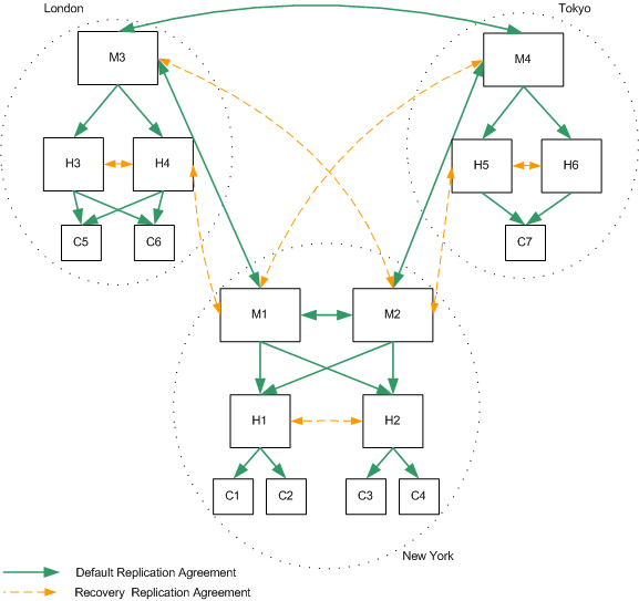
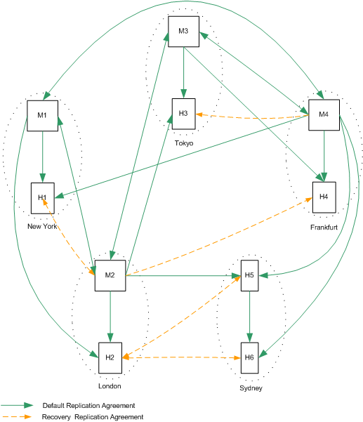
As was the case for two data centers, if more than one master fails, a recovery strategy involving the creation of recovery replication agreements is required. These agreements are disabled by default but can be enabled rapidly in the event of a failure, as shown in Figure 10-13.
Figure 10-13 Three Data Centers Recovery Replication Agreements
Three Data Centers Recovery Procedure (One Component)
In the scenario depicted in Figure 10-13, losing one master in either London or Tokyo implies that local write capability is lost. The following procedure assumes that M3 (London) has failed.
- Promote H4 to a writable master. For information on how to do this, refer to "Promoting or Demoting Replicas" in the Sun ONE Directory Server Administration Guide.
- Enable the recovery replication agreement from H4 to H3, to ensure that local writes are replicated to all local consumers.
- Enable the recovery replication agreements between M1 and H4 to ensure that local writes are replicated to remote data centers and that remote writes are replicated to local consumers.
- Ensure that any applications that were accessing M3 are redirected to point to the new master.
Note This procedure is an intermediate solution that will provide immediate local read and write capability, while you set about repairing M3.
Five Data Centers
Sun ONE Directory Server 5.2 supports 4-way multi-master replication. In an enterprise spread over five main geographical regions, you must assess which region has the lowest requirements in terms of local update performance. This region will not have a master server and will redirect writes to one of the masters in the other regions.
Five Data Centers Basic Topology
The topology depicted in Figure 10-14 assumes that the Sydney data center receives the smallest number of write requests. Local read requests are possible in each of the five data centers.
Figure 10-14 Five Data Centers Basic Topology
Five Data Centers Scaled For Read Performance
As in the previous scenarios, increased read performance is achieved by adding hubs and consumers, once again taking into account the anticipated performance requirements across the different data centers.
Five Data Centers Recovery Scenarios
As was the case for two data centers, if more than one master fails, a recovery strategy involving the creation of recovery replication agreements is required. These agreements are disabled by default but can be enabled rapidly in the event of a failure, as shown in Figure 10-15.
Five Data Centers Recovery Procedure (One Component)
In the scenario depicted in Figure 10-15, losing a master in any data center implies that local write capability is lost. The following procedure assumes that M1 (New York) has failed.
- Promote H1 to a writable master. For information on how to do this, refer to "Promoting or Demoting Replicas" in the Sun ONE Directory Server Administration Guide.
- Enable the recovery replication agreement from M2 to H1, to ensure that local writes are replicated to remote data centers and that remote writes are replicated to local consumers.
- Ensure that any applications that were accessing M1 are redirected to point to the new master.
Note This procedure is an intermediate solution that will provide immediate local read and write capability, while you set about repairing M1.
Figure 10-15 Five Data Centers Recovery Replication Agreements
Single Data Center Using the Retro Change Log Plug-In
The previous topology for a single data center does not take into account the use of the retro change log plug-in. Compatibility with this plug-in implies that a multi-master replication topology can not be deployed. For more information on the retro change log plug-in, refer to Using the Retro Change Log Plug-In in the Sun ONE Directory Server Administration Guide.
Retro Change Log Plug-in Basic Topology
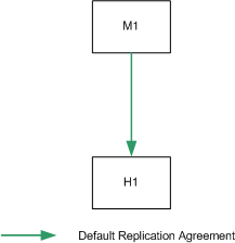
If multi-master replication cannot be deployed, the basic topology depicted in Figure 10-16 is suggested.
Figure 10-16 One Data Center Using the Retro Change Log Plug-in
Retro Change Log Plug-in Scaled For Read Performance
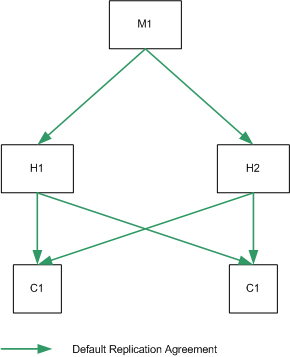
As in the standard single data center topology, increased read performance is achieved by adding hubs, and then consumers, as indicated in Figure 10-17.
Figure 10-17 One Data Center Using the Retro Change Log Plug-in (Scaled)
Retro Change Log Plug-in Recovery Procedure
For the deployment depicted in Figure 10-17, the following strategy can be applied if the master server fails:
- Stop M1 (if it is not already stopped).
- Promote H1 or H2 to a master server. For information on how to do this, refer to "Promoting or Demoting Replicas" in the Sun ONE Directory Server Administration Guide.
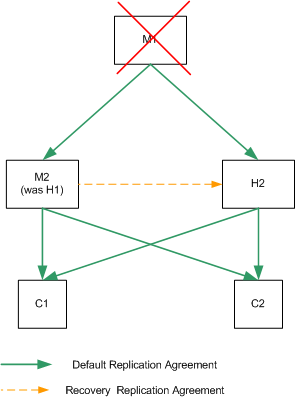
- Enable the retro change log plug-in on the new master (M2.)
- Restore the backup of the retro change log on M2.
- Restart the server.
- Add a replication agreement between M2 and the remaining hub to ensure that modifications continue to be replicated to the hub.
This recovery strategy is illustrated in Figure 10-18.
Figure 10-18 One Data Center Using the Retro Change Log Plug-in (Recovery)
