| C H A P T E R 1 |
|
Introduction |
This chapter includes the following sections:
The Sun Netra CT900 server shelf software includes:
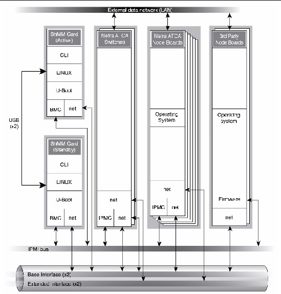
The software is described in TABLE 1-1 and represented logically, with the hardware, in FIGURE 1-1.
The Sun Netra CT900 server has two shelf management cards (ShMMs) and provides shelf management card failover from the active shelf management card to the backup shelf management card for certain hardware and software events. The active shelf management card is used for system-level configuration, administration, and management of most of the components connected to the midplane. The backup shelf management card provides redundancy and failover capability for the active shelf management card.
The switching fabric boards connect the shelf management card and the node boards internally, and have Ethernet ports on the rear for external connectivity.
Some Sun Netra ATCA node boards and rear transition modules (RTMs) accept peripherals, such as disks. The Sun Netra ATCA node boards also run user applications. In a Sun Netra CT 900 server, each node board runs its own copy of an operating system, and each is therefore considered a server. The shelf management cards, node boards, switching fabric boards, and the other system field-replaceable units (FRUs) make up a system.
TABLE 1-2 summarizes how you can access the various boards. The shelf management card supports 22 sessions (1 Tip and 21 Telnet connections) at one time
The hardware interfaces include the Intelligent Platform Management Interface (IPMI), the base interface and extended interface, and the network interface on the shelf management cards, the node boards, and the switching fabric boards.
FIGURE 1-1 Logical Representation of Software and Hardware Interfaces in Sun Netra CT900 Server

The Shelf Manager is a shelf-level management solution for ATCA products. The shelf management card provides the necessary hardware to run the Shelf Manager within an ATCA shelf. This overview focuses on aspects of the Shelf Manager and shelf management card that are common to any shelf management carrier used in an ATCA context.
The Shelf Manager and shelf management card are Intelligent Platform Management (IPM) building blocks designed for modular platforms like ATCA, in which there is a strong focus on a dynamic population of FRUs and maximum service availability. The IPMI specification provides a solid foundation for the management of such platforms, but requires significant extension to support them well. PICMG 3.0, the ATCA specification, defines the necessary extensions to IPMI.
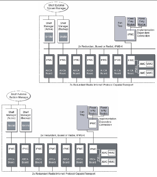
FIGURE 1-2 shows the logical elements of an example ATCA shelf, identified in terms of the ATCA specification.
An AdvancedTCA Shelf Manager communicates inside the shelf with IPM Controllers, each of which is responsible for local management of one or more field replaceable units (FRUs), such as boards, fan trays or power entry modules. Management communication within a shelf occurs primarily over the Intelligent Platform Management Bus (IPMB), which is implemented on a dual-redundant basis as IPMB-0 in AdvancedTCA.
The PICMG Advanced Mezzanine Card (AdvancedMC or AMC) specification, AMC.0, defines a hot-swappable mezzanine form factor designed to fit smoothly into the physical and management architecture of AdvancedTCA.
FIGURE 1-2 includes an AMC carrier with an IPMC and two installed AMC modules, each with a Module Management Controller (MMC). On-carrier management communication occurs over IPMB-L ("L" for Local).
FIGURE 1-2 Example of ATCA Shelf

An overall System Manager (typically external to the shelf) can coordinate the activities of multiple shelves. A System Manager typically communicates with each Shelf Manager over an Ethernet or serial interface.
FIGURE 1-2 shows three levels of management: board, shelf, and system. The next section addresses the Shelf Manager software and card which implement an ATCA-compliant shelf manager (ShMM).
The Shelf Manager (consistent with ATCA Shelf Manager requirements) has two main responsibilities:
Much of the Shelf Manager software is devoted to routine missions such as powering a shelf up or down and handling the arrival or departure of FRUs, including negotiating assignments of power and interconnect resources. In addition, the Shelf Manager can take direct action when exceptions are raised in the shelf. For instance, in response to temperature exceptions the Shelf Manager can raise the fan levels or, if that step is not sufficient, even start powering down FRUs to reduce the heat load in the shelf.
The Shelf Manager software features include:
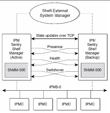
The Shelf Manager can be configured with active/backup instances to maximize availability. FIGURE 1-3 shows how both instances are accessible to the System Manager, with only the active instance interacting at any given time. Similarly, only the active instance communicates over IPMB-0 with the IPM controller population in the shelf. The two instances communicate with each other over TCP/IP, with the active instance posting incremental state updates to the backup. As a result, the backup can quickly step into the active role if necessary.
FIGURE 1-3 Shelf Manager Switchover Signal

TABLE 1-3 list the signals and descriptions.
The active Shelf Manager exposes the ShMM device (address 20h) on IPMB, manages IPMB and the IPM controllers, and interacts with the System Manager over RMCP and other shelf-external interfaces. It maintains an open TCP connection with the backup Shelf Manager. It communicates all changes in the state of the managed objects to the backup Shelf Manager.
The backup Shelf Manager does not expose the ShMM on IPMB, does not actively manage IPMB and IPM controllers, and does not interact with the System Manager via the shelf-external interfaces (with one exception noted below). Instead, it maintains the state of the managed objects in its own memory (volatile and non-volatile) and updates the state as directed by the active Shelf Manager.
The backup Shelf Manager can become active as the result of a switchover. Two types of switchover are defined:
The backup Shelf Manager recognizes the departure of the active Shelf Manager when the Remote Healthy or Remote Presence low-level signal becomes inactive. The Remote Presence signal monitors the presence of the peer Shelf Manager; this signal going inactive means that the board hosting the peer Shelf Manager has been removed from the shelf. The Remote Healthy signal is set by the peer Shelf Manager during initialization; this signal going inactive means that the remote Shelf Manager has become unhealthy (typically, has been powered off or reset).
Another situation that needs some action from the backup Shelf Manager is when the TCP connection between the Shelf Managers gets closed. This happens when the communication link between the two Shelf Managers is broken, when the shelf management process on the active Shelf Manager terminates (either voluntarily or involuntarily), or when a software exception occurs. Since the TCP keepalive option is enabled on the connection, it closes shortly after the active shelf management card is switched off or reset.
In the case of Shelf Manager termination, it is possible that the TCP connection is closed before the Remote Healthy signal becomes inactive. To determine why the TCP connection closed, the backup Shelf Manager samples the state of the Remote Healthy signal immediately and, if it is still active, again after some delay. When the Remote Healthy signal finally goes inactive, the backup Shelf Manager concludes that the active Shelf Manager is dead, and initiates a switchover.
If the Remote Healthy signal stays active, the backup Shelf Manager concludes that the communication link between the Shelf Managers is broken. In that case, no switchover is initiated; instead, the backup Shelf Manager repeatedly reinitializes itself and tries to establish a connection with the active Shelf Manager, until the communication link is restored. Reinitialization is achieved by rebooting the shelf management card and automatically restarting the Shelf Manager after the reboot. Special logic in the Shelf Manager guarantees that it does not try to become active at startup if the peer Shelf Manager is already active.
The Shelf Manager uses a watchdog timer to protect against becoming unresponsive due to infinite loops or other software bugs. If the watchdog timer on the active Shelf Manager triggers, that shelf management card is reset, causing the Remote Healthy signal on the backup shelf management card to become inactive, thus triggering a switchover.
After a switchover, the now-active Shelf Manager reinitalizes, activates the cached state information, and collects the necessary information from the IPM controllers on IPMB. This active Shelf Manager then exposes the ShMC device (address 20h) on IPMB, and assumes the IP address that was used for RMCP and other shelf-external interactions between the formerly active Shelf Manager and the System Manager. Since the RMCP session information is propagated from the active Shelf Manager to the backup Shelf Manager, RMCP sessions survive the switchover. For the System Manager using RMCP, the switchover is transparent.
After the switchover the formerly active Shelf Manager can cease to exist or reinitialize itself as the backup Shelf Manager. Reinitializing as the backup Shelf Manager requires rebooting the operating system on the formerly active shelf management card.
Another major subsystem of the Shelf Manager implements the System Administrator Interface. The System Administrator is a logical concept that can include software as well as human operators in an operations center. The Shelf Manager provides two System Administrator interface options that provide different mechanisms of access to similar kinds of information and control regarding a shelf:
The IPMI LAN interface is used to maximize interoperability among independently implemented shelf products. This interface is required by the ATCA specification and supports IPMI messaging with the Shelf Manager through RMCP. A System Administrator that uses RMCP to communicate with shelves should be able to interact with any ATCA-compliant Shelf Manager. This low-level interface provides access to the IPMI aspects of a shelf, including the ability for the System Administrator to issue IPMI commands to IPM controllers in the shelf, using the Shelf Manager as a proxy.
RMCP is a standard network interface to an IPMI controller via LAN and is defined by the IPMI 1.5 specification.
The CLI provides a comprehensive set of textual commands that can be issued to the Shelf Manager through either a physical serial connection or a Telnet connection.
Sun Netra CT900 server system administration typically includes installation, configuration, and administration tasks.
Oracle Solaris OS administration on the Sun Netra CT900 server, including adding Oracle Solaris user accounts, is performed by logging into the node board. Server administration is performed by logging into the shelf management card and using the shelf management card CLI. The shelf management card can be used as the single point of entry in the Sun Netra CT900 server for configuration and administration purposes.
System administration tasks are described in the following chapters.
When viewing the Sun Netra CT900 server from the front, the physical slots are sequentially numbered from left to right. TABLE 1-4 shows the physical-to-logical-slot mapping and addresses. TABLE 1-5 lists the shelf’s physical address and associated FRUs.
Copyright © 2011, Oracle and/or its affiliates. All rights reserved.