| C H A P T E R 1 |
|
Programming Environment |
This chapter provides an overview of the software environment that forms the basis for developing applications for the Sun Netra CT900 server:
The Netra CT 900 server is an Advanced Telecom Computing Architecture (AdvancedTCA® or ATCA) packet-switching, backplane-based, rackmountable server.
The Netra CT 900 server complies with the following specifications:
The hardware components for the Netra CT 900 server can be broken down into four sections:
This section contains descriptions of the major components of the Sun Netra CT900 server.
The shelf features twelve node board slots and a redundant infrastructure (switch, management, power, and cooling), making it ideal for carrier-grade telecom and Internet applications. Beyond its high-availability features, the Netra CT 900 server is highly modular, scalable, and serviceable.
Hot-swappable system components provide built-in redundancy to simplify replacement and minimize service time. Redundant shelf management cards enable customers to manage multiple processor boards and conduct shelf diagnostics remotely for enhanced system reliability. Two 8U slots are reserved for PICMG 3.0/3.1 switches. The Netra CT 900 server routes Ethernet signals across the midplane without the use of cables, saving time in setup, maintenance, and repair, and eliminating the thermal challenges of traditional cabling methods.
The shelf alarm panel (SAP) is a removable module mounted at the top right side of the shelf, above slots 9 through 14 in the shelf. It provides the connectors for the serial console interfaces of the shelf management cards, the telco alarm connector, the Telco Alarm LEDs, the user-definable LEDs, and the Alarm Silence push button.
The I2C-bus devices on the shelf alarm panel are connected to the master-only I2C-bus of both shelf management cards. Only the active shelf management card has access to the shelf alarm panel.
The Netra CT 900 server has two dedicated slots for the shelf management cards. Each shelf management card is a 78 mm by 280 mm form factor board with a SODIMM socket for the shelf management mezzanine (ShMM) device. The Netra CT 900 server has radial IPMBs and is designed to work with two redundant shelf management cards. The shelf management card also contains the fan controller for the three hot-swappable fan trays, and provides individual Ethernet connections to both switches.
The dual-IPMB interface from the ShMM is connected to the dual IPMBs on an ATCA node board through radial connections in the Netra CT 900 server midplane. Each shelf management card has an Ethernet port that is not available to the user; instead, Ethernet traffic from the shelf management card is routed to the Ethernet ports on the switches. Serial and telco alarm traffic from the shelf management card are routed to the ports and LEDs on the shelf alarm panel.
The shelf management card includes several on-board devices that enable different aspects of shelf management based on the ShMM. These facilities include I2C-based hardware monitoring and control and General Purpose Input/Output (GPIO) expander devices.
The switch for the Netra CT 900 server is an AdvancedTCA 3.0 and 3.1 Option 1 switch. This means that the switch implements two separate switched networks on a single printed circuit board (PCB). By separating the Base (3.0) and Extended Fabric (3.1) networks, the switch provides a separate control plane and data plane. It provides 10/100/1000BASE-T Ethernet switching on the 3.0 Base Fabric interface and on the 3.1 Extended Fabric interface it provides 1000BASE-X Ethernet switching. Both of these networks are fully managed and work with the robust FASTPATH management suite. Both networks support Layer 2 switching as well as Layer 3 routing. The switch also supports a rear transition module to expand connectivity with uplink ports.
The Sun Netra CT900 server software includes:
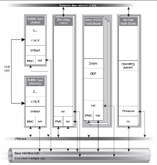
The software is described in TABLE 1-1 and represented logically, with the hardware, in FIGURE 1-1.
FIGURE 1-1 Logical Representation of Software and Hardware Interfaces in a Sun Netra CT900 Server
The Shelf Manager is a shelf-level management solution for ATCA products. The shelf management card provides the necessary hardware to run the Shelf Manager within an ATCA shelf. This overview focuses on aspects of the Shelf Manager and shelf management card that are common to any shelf management carrier used in an ATCA context.
The Shelf Manager and shelf management card are Intelligent Platform Management (IPM) building blocks designed for modular platforms like ATCA, in which there is a strong focus on a dynamic population of FRUs and maximum service availability. The IPMI specification provides a solid foundation for the management of such platforms, but requires significant extension to support them well. PICMG 3.0, the ATCA specification, defines the necessary extensions to IPMI.
An AdvancedTCA Shelf Manager communicates inside the shelf with IPM Controllers, each of which is responsible for local management of one or more field replaceable units (FRUs), such as boards, fan trays or power entry modules. Management communication within a shelf occurs primarily over the Intelligent Platform Management Bus (IPMB), which is implemented on a dual-redundant basis in AdvancedTCA.
The PICMG Advanced Mezzanine Card (AdvancedMC or AMC) specification, AMC.0, defines a hot-swappable mezzanine form factor designed to fit smoothly into the physical and management architecture of AdvancedTCA.
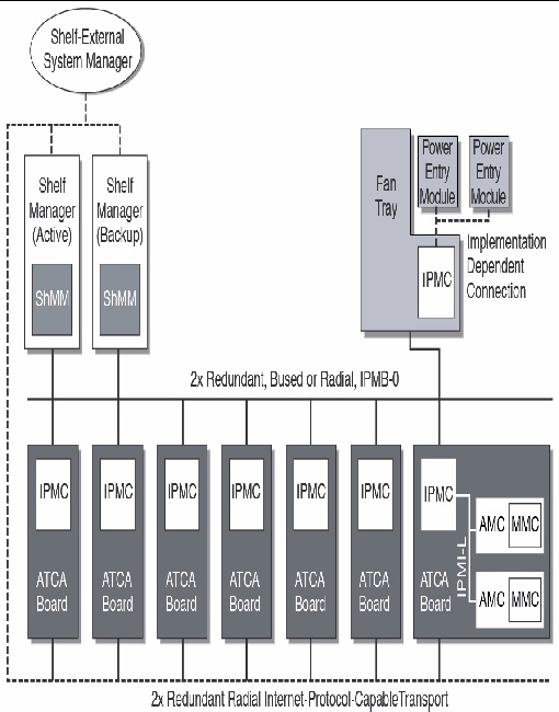
FIGURE 1-2 includes an AMC carrier with an IPMC and two installed AMC modules, each with a Module Management Controller (MMC). On-carrier management communication occurs over IPMB-L ("L" for Local).
FIGURE 1-2 Example of ATCA Shelf
An overall system manager (typically external to the shelf) can coordinate the activities of multiple shelves. A system manager typically communicates with each Shelf Manager over an Ethernet or serial interface.
FIGURE 1-2 shows three levels of management: board, shelf, and system. The next section addresses the Shelf Manager software and shelf management card which implement an ATCA-compliant shelf manager and shelf management controller (ShMC).
The Shelf Manager (consistent with ATCA Shelf Manager requirements) has two main responsibilities:
Much of the Shelf Manager software is devoted to routine missions such as powering a shelf up or down and handling the arrival or departure of FRUs, including negotiating assignments of power and interconnect resources and monitoring the health status of each FRU. In addition, the Shelf Manager can take direct action when exceptions are raised in the shelf. For instance, in response to temperature exceptions the Shelf Manager can raise the fan levels or, if that step is not sufficient, even start powering down FRUs to reduce the heat load in the shelf.
The Shelf Manager software features include:
Each manageable component of the system is identified as a unique entity in the system. Every entity is uniquely named by an entity path that identifies the component in terms of its physical containment within the system.
An entity path consists of an ordered set of {Entity Type, Entity Location} pairs. The path defines the physical location of the entity in the system, in terms of which entity it is contained within and the entity that its container is contained in.
For more details, refer to the SAF-HPI-B.01.01 specification. You can obtain the specification at:
Appendix A contains a presentation of the abbreviated resource table of a Sun Netra CT900 server, which contains two ShMM 500 shelf managers, two CT3140 switch blades, one CP3010 blade, one CP3020 blade, and one CP3060 blade.
Appendix B contains the resource data records for the 3.2 PICMG blades. The resource data records define the management instruments (sensors, controls, watchdog timers, inventory data repositories, or annunciators) associated with a resource.
Another major subsystem of the Shelf Manager implements the System Administrator interface. The System Administrator is a logical concept that can include software as well as human operators in an operations center. The Shelf Manager provides two System Administrator interface options that provide different mechanisms of access to similar kinds of information and control regarding a shelf:
The IPMI LAN interface is used to maximize interoperability among independently implemented shelf products. This interface is required by the ATCA specification and supports IPMI messaging with the Shelf Manager through RMCP. A system administrator who uses RMCP to communicate with shelves should be able to interact with any ATCA-compliant Shelf Manager. This low-level interface provides access to the IPMI aspects of a shelf, including the ability for the system administrator to issue IPMI commands to IPMI controllers in the shelf, using the Shelf Manager as a proxy.
RMCP is a standard network interface to an IPMI controller through the LAN and is defined by the IPMI 1.5 specification.
The CLI provides a comprehensive set of textual commands that can be issued to the Shelf Manager through either a physical serial connection or a Telnet connection.
The Open Hardware Platform Interface (OpenHPI) defines a C application programming interface to access platform management capabilities, such as:
For a detailed description of the OpenHPI, along with supported return codes, refer to the OpenHPI specification at:
The Service Availability Forum (SAF) Hardware Platform Interface (HPI) specifies a generic mechanism to monitor and control highly available systems. The ability to monitor and control these systems is provided through a consistent, platform independent set of programmatic interfaces. The HPI specification provides data structures and functional definitions you can use to interact with manageable subsets of a platform or system. The HPI allows applications and middleware to access and manage hardware components through a standardized interface.
The HPI model includes four basic concepts: entities, resources, sessions, and domains. Each of these concepts is described briefly in this section.
Entities represent the physical components of the system. Each entity has a unique identifier, called an entity path, which is defined by the component’s location in the physical containment hierarchy of the system.
Resources provide management access to the entities within the system. Frequently, resources represent functions performed by a local control processor used for management of the entity’s hardware. Each resource is responsible for presenting a set of management instruments and management capabilities to the HPI User. Resources can be dynamically added and removed in a system as hot-swappable system components that include management capabilities are added and removed.
Sessions provide all access to an HPI implementation by HPI users. An HPI session is opened on a single domain; one HPI user can have multiple sessions open at once, and there can be multiple sessions open on any given domain at once. Sessions also provide access to events created or forwarded by the domain accessed by the session. An HPI user accesses the system through sessions, where each session is opened on a domain. A session provides access to domain functions and to a set of resources that are accessible through the domain.
All HPI user functions are accessed through sessions, and each session is associated with a single domain. A domain provides access to zero or more resources and provides a set of associated services and capabilities. The latter are logically grouped into an abstraction called a domain controller. The resources that are accessible through a domain are listed in the domain’s Resource Presence Table (RPT). The contents of this table can change over time, and the domain’s session management capability rejects any attempt to access a resource that is not currently listed in the domain’s Resource Presence Table.
As shown in FIGURE 1-3, the management application talks to the OpenHPI daemon through the OpenHPI library. The OpenHPI daemon talks to the platform (local or remote) through the plug-ins.
FIGURE 1-3 OpenHPI Architecure
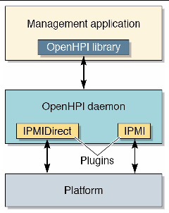
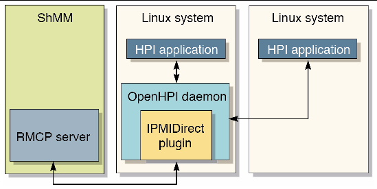
FIGURE 1-4 shows a Linux OS system running the OpenHPI daemon (IPMI direct
plug-in), communicating with the ShMM over RMCP for shelf management.
FIGURE 1-4 HPI Applications, OpenHPI Daemon, and RMCP Server Relationships
The SAF HPI draws heavily on the concepts set forth by the Intelligent Platform Management Interface (IPMI) specification to define platform-independent capabilities and data formats. Thus, an implementation of the HPI interface on a platform that uses IPMI as a platform management infrastructure can be very straightforward. However, because HPI is a generic interface specification, it can be implemented on any platform with sufficient underlying platform management technology.
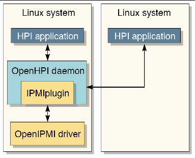
FIGURE 1-5 shows the OpenHPI daemon (IPMI plug-in) running on a system with an OpenIPMI driver for local management.
FIGURE 1-5 HPI Application and OpenIPMI Driver Relationships
Copyright © 2011, Oracle and/or its affiliates. All rights reserved.