JavaScript is required to for searching.
Skip Navigation Links
Exit Print View
Sun Storage 6 Gb SAS PCIe RAID HBA, Internal

Installation Guide For HBA Models SGX-SAS6-R-INT-Z and SG-SAS6-R-INT-Z

Oracle Technology Network
Library
PDF
Print View
Feedback
search filter icon
search icon

Document Information

Using This Documentation

Chapter 1 HBA Overview

Chapter 2 Hardware Installation and Removal

Chapter 3 Creating a Bootable Drive in a Preboot Environment

Chapter 4 HBA Software Installation

Chapter 5 Known Issues

Appendix A HBA Specifications

Physical Dimensions

HBA Card Layout

HBA Jumpers and Connectors

Environmental Specifications

Fault Tolerance

Electrical Characteristics

Glossary

HBA Specifications

This appendix contains the specifications for the HBA.

This appendix contains the following topics:

Physical Dimensions

The HBA card size is as follows:

Height: 94.31mm (2.731 inches)

Length: 167.64mm (6.6 inches)

HBA Card Layout

The HBA controls eight internal SAS/SATA ports through two SFF-8087 x4 internal mini SAS connectors. HBA Card Layout shows the jumpers and connectors on the HBA.

Figure A-1  HBA Card Layout
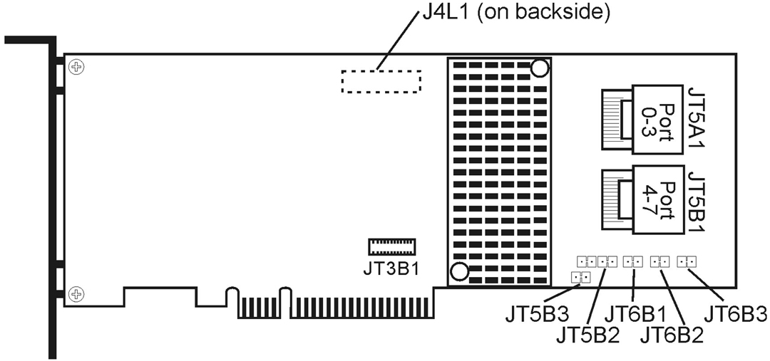
image:The graphic shows the connectors on the Sun Storage 6 Gb/s SAS PCIe RAID HBA, Internal.

HBA Jumpers and Connectors

HBA Jumpers and Connectors describes the jumpers and the connectors on the HBA.

Table A-1  HBA Jumpers and Connectors
Connector
Description
Comments
JT3B1
Battery Backup connector
20-pin connector
Connects the LSIiBBU08 intelligent Battery Backup Unit directly to the RAID controller.
JT5A1
x4 SAS Ports 0–3 Mini SAS 4i connector
Mini SAS 4x connector
Connects the cables from the controller to SAS drives or SATA II drives, or to a SAS expander.
JT5B1
x4 SAS Ports 4–7 Mini SAS 4i connector
Mini SAS 4x connector
Connects the cables from the controller to SAS drives or SATA II drives, or to a SAS expander.
JT5B2
Universal Asynchronous Receiver/Transmitter (UART) debugging
4-pin connector
Reserved for Oracle use.
JT5B3
Set Factory Defaults connector
2-pin connector
Returns the board settings to the defaults set in the factory.
JT6B1
LSI Test header
2-pin connector
Reserved for Oracle use.
JT6B2
Global Drive Fault LED header
2-pin connector
Connects to an LED that indicates whether a drive is in a fault condition.
JT6B3
SAS Activity LED
header
2-pin connector
Connects to an LED that indicates drive activity.

Environmental Specifications

The HBA environmental requirements are listed in HBA Environmental Specifications.

Table A-2  HBA Environmental Specifications
Specification
Operating
Non-Operating
Temperature
  • +10˚C to +60˚C without battery backup unit

  • +10˚C to +55˚C with iBBU battery backup

  • -30˚C to +80˚C without battery backup unit

  • 0˚C to +56˚C with iBBU battery backup

Humidity
5% to 90% RH, noncondensing, 40˚C max, 27˚C max wet bulb, 16 hour dwells at extreme
93% RH, noncondensing, 40˚C max, 120 hours
Altitude
3200m at 40˚C, 4 hour dwell
12,200m at 0˚C, 4 hour dwell
Vibration
0.25G in all axes swept for 5-500-5 Hz, 5 sweeps in all at 1 octave/min
1.2G in all axes swept for 5-500-5 Hz, 5 sweeps in all at 1 octave/min
Shock
5.5G, 11 ms half-sine, 10 shocks in x-, y-, and z-axes
33G, 11 ms half-sine, 3 shocks in x-, y-, and z-axes
Airflow
At least 200 linear feet per minute (LFPM)

Fault Tolerance

Fault Tolerance Features  lists the fault tolerance features for the HBA.

Table A-3  Fault Tolerance Features 
Specification
HBA
Support for SMART

The Self Monitoring Analysis and Reporting Technology (SMART) detects up to 70 percent of all predictable drive failures. In a-ddition, SMART m-onitors the internal p-erformance of all motors, heads, and drive el-ectronics.

Yes
Optional battery backup for cache memory
LSIiBBU08 battery backup. <3.7V/1350mAH battery pack; up to 48 hours of data retention for 512 Mbytes
Drive failure detection
Automatic
Drive rebuild using hot spares
Automatic
Parity generation and checking
Yes

Electrical Characteristics

All power is supplied to the HBA through the PCI Express 3.3V rails and the 12V rail. Onboard switching regulator circuitry operating from the 3.3V rails and the 12V rail provide the necessary voltages. The following states determine the typical current consumption of the controller:

The supply voltages are 12V 8 percent (from PCI edge connector only) and 3.3V 9 percent (from PCI edge connector only). Power Supply for the HBA lists the power supply information for the controller for each of the three states at the different voltages.

Table A-4  Power Supply for the HBA
PCI Edge Connector
State 1
State 2
State 3
3.3V supply
330mA
330mA
330mA
+12V supply
1.00A
1.81A
1.53A
3.3V auxiliary supply
30mA
30mA
30mA

+12V is used in the charging circuitry for the battery pack on the optional iBBU battery-backed daughter card. If the iBBU daughter card is mounted, the following power consumption figures apply: During fast charging of the battery pack: 230mA in +12V current