| C H A P T E R 6 |
 Returning the Server to Operation
 |
This chapter describes how to return the Sun Fire X4270 M2 Server to operation after you have performed service procedures.
The following topics are covered in this chapter:

|
Caution - Hazardous voltage present.Never attempt to run the server with the covers removed. |

|
Caution - Equipment damage possible.Covers must be in place for proper airflow. |
| Note - This procedure only applies to servers with 2.5-inch storage drives. |
| Note - Servicing some components requires that the server’s front cover be removed. |
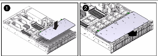
1. Position the front cover over the front of the server so that there is about a 0.25 inch (6 mm) of clearance between the front edge of the cover and the front of the server [1].
2. Slide the front cover toward the front of the server until the release levers on the back of the front cover are fully engaged [2].
The release levers will click when they are fully engaged.
FIGURE 6-1 Installing the Front Cover
If you removed the top cover, perform the following procedure to replace it.
1. Place the top cover on the chassis (FIGURE 6-2 [1]).
a. Set the cover down so that it hangs over the rear of the server by about 1 inch (25.4 mm).
b. Ensure that the rear interlocks on both sides of the top cover engage the slots on both sides of the server’s chassis.
FIGURE 6-2 Installing the Top Cover on the Sun Fire X4270 M2 Server
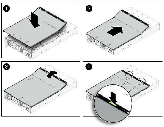
2. Slide the top cover forward until it seats [2].
4. Press down on the cover at the locations labeled to close the cover completely [4].
If you removed the server chassis from the rack, perform these steps.

|
Caution - The servers are heavy. Two people might be required to carry the chassis and install it in the rack.
|
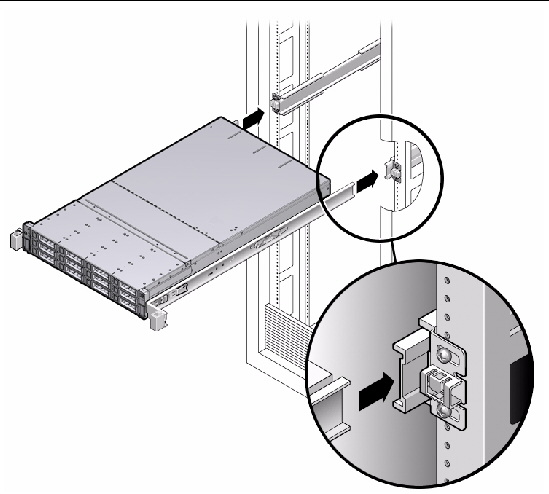
1. Push the slide-rails into the slide-rail assemblies in the rack as far as possible.
2. Raise the server so that the rear ends of the mounting brackets are aligned with the slide-rail assemblies that are mounted in the rack (FIGURE 6-3).
3. Insert the mounting brackets into the slide-rails, then push the server into the rack until the mounting brackets encounter the slide-rail stops (approximately 12 inches, or 30 cm).
The server is now in the extended maintenance position.
FIGURE 6-3 Returning the Server to the Rack
If you extended the server to the maintenance position, use this procedure to return the server to the normal rack position.
1. Release the slide rails from the fully extended position by pushing the release tabs on the side of each rail (FIGURE 6-4).
FIGURE 6-4 Release Tabs on Rails
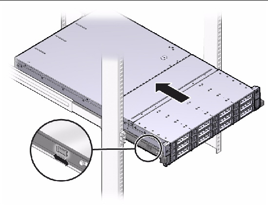
2. Simultaneously push and hold the slide-rail release buttons on each mounting bracket while you push the server into the rack.
Ensure that the cables do not get in the way.
3. Continue pushing until the slide-rail locks (on the front of the mounting brackets) engage the slide-rail assemblies.
You will hear an audible click when the server is in the normal rack position.
4. Reconnect the cables to the back of the server.
If the cable management arm (CMA) is in the way, disconnect the left CMA release and swing the CMA open.
Swing the CMA closed and latch it to the left rack rail.
Before powering on your server for the first time, follow the installation and cabling instructions provided in the Sun Fire X4170 M2 and X4270 M2 Servers Installation Guide (821-0481), which is optionally shipped with the system and is also available online at:
http://docs.sun.com/app/docs/prod/sf.x4270m2#hic
To connect power cords and apply power to the server:
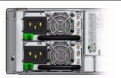
1. Connect the power cord (or cords) to the power supply (or supplies) on the server’s rear panel (FIGURE 6-5).
FIGURE 6-5 Rear Panel Power Supplies
2. Verify that standby power is on.
In standby power mode, the Power/OK LED on the front panel next to the Power button flashes. See FIGURE 1-1 for the location of the Power/OK LED.
3. Press and release the recessed Power button on the server front panel.
When the main power is applied to the server, the Power/OK LED lights and remains lit, as shown in FIGURE 1-1.

Copyright © 2011, Oracle and/or its affiliates. All rights reserved.