| C H A P T E R 3 |
|
Telco Rackmounting |
This section provides the procedures for mounting a Sun StorEdge 3000 Family 1U array using Telco hardware.
The following tools are used to complete these procedures:

|
Caution - Do not use any power tools with any procedures. Power tools can strip or damage connections. |
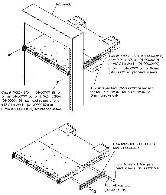
Before mounting the array into a 19-inch cabinet, check the following parts list and then refer to FIGURE 3-1 during installation.
The following table lists the major components and fasteners required to assemble the Telco 19-inch wide flushmount racks.
Perform the following installation steps for a Telco flushmount rack configuration (see FIGURE 3-1).
1. Determine the position at which the array will be installed.
Install the first array at the bottom of the rack, and install each subsequent chassis above the one below it.
2. Before rackmounting, be sure to check your site location and confirm that you have cables with adequate lengths to connect to servers and to power outlets.
3. Remove bezel (front faceplate) and two plastic ear caps from the front of the chassis.
To remove a plastic ear cap (both caps are removed the same way):
a. Grasp both sides of the cap.
b. With minimal force, pull the cap straight out from the array until it disengages.
|
Note - Keep all hardware items in plastic bags until you are ready to use them. This will enable you to correctly identify the screws and avoid confusion. |
4. While supporting the chassis, attach the unit to the Telco rack, using two mounting screws through the chassis ears.
Use the appropriate type of screws:
5. Attach the rear brackets to the left and right sides of the chassis. Use four #8-32 x 1/4-inch panhead machine screws (01-000000186) with #8 washers (02-00000019) per bracket.
Use the appropriate type of screws for the posts:
6. Reinstall all drive modules and power/fan modules into the array if they were removed.
7. Reattach the two plastic ear caps and the bezel onto the front of the chassis.
Each plastic cap is replaced the same way, but be sure the cap with the LED labels on the right ear.
a. Align the inside round notches of the cap with the round cylindrical posts (ball studs) on the ear.
b. Push the top and bottom of the ear cap onto the ear, pressing in toward the center of the array.
c. Continue pushing the top and bottom of the ear cap onto the ear until the ear cap snaps in flush.
Do not use force when placing a cap on an ear.

|
Caution - Be careful to avoid "wedging" the reset button below the LEDs on the right ear when you replace the plastic cap over it. |
d. Insert the bezel swing arms into the chassis ear holes.
e. Lift the bezel into position and press it onto the front of the chassis until it is flush with the front.
f. Use the key to lock both bezel locks.
8. Connect the power cables to the chassis, power on, and check for proper operation of the LEDs.
For details on powering on and checking LEDs, see Chapter 4.
Refer to the Sun StorEdge 3000 Family Installation, Operation, and Service Manual to see more information about cable connections and LED functionality.
|
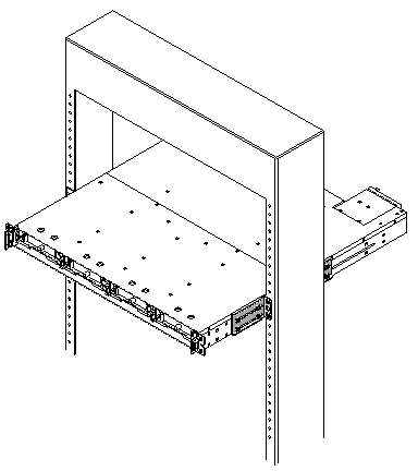
Note - Not all racks allow mountings in the location shown in the following figure. |

The following table lists the major components and fasteners required to assemble the Telco 19-inch wide center-of-gravity rack.

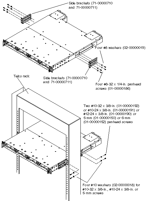
Perform the following installation steps for a Telco center-of-gravity rack configuration (see FIGURE 3-3).
1. Determine the position at which the array will be installed.
Install the first array at the bottom of the rack, and install each subsequent chassis above the one below it.
2. Before rackmounting, be sure to check your site location and confirm that you have cables with adequate lengths to connect to servers and to power outlets.
|
Note - Keep all hardware items in plastic bags until you are ready to use them. This will enable you to correctly identify the screw sizes and avoid confusion. |
3. Remove the bezel (front faceplate) and two plastic ear caps from the front of the chassis.
To remove a plastic ear cap (both caps are removed the same way):
a. Grasp both sides of the cap.
b. With minimal force, pull the cap straight out from the array until it disengages.
4. Attach the two side brackets to each side of the chassis:
Allow for the depth of the rack, and allow for the distance you want the chassis to extend forward in the rack. Attach the front brackets first.
Use up to six #8-32 x 1/4-inch panhead machine screws (01-00000186) with #8 washers (02-00000019) for each side bracket, using the mounting holes available. (Use four screws as a minimum.) Then mount the side brackets to the Telco rack using step 5.
5. Attach the chassis to the Telco rack, by inserting eight or more screws through the mounting holes located on both sides of the brackets and into the frame. (See FIGURE 3-3.)
Use the appropriate type of screws for the ports:
Next, use four #8-32 x 1/4-inch panhead screws (01-00000186) with #8 washers (02-00000019) for each side bracket.
6. Reinstall all drive modules and power/fan modules into the array if they were removed.
7. Reattach the two plastic ear caps and the bezel onto the front of the chassis.
Each plastic cap is replaced the same way, but be sure the cap with the LED labels on the right ear.
a. Align the inside round notches of the cap with the round cylindrical posts (ball studs) on the ear.
b. Push the top and bottom of the ear cap onto the ear, pressing in toward the center of the array.
c. Continue pushing the top and bottom of the ear cap onto the ear until the ear cap snaps in flush.
Do not use force when placing a cap on an ear.

|
Caution - Be careful to avoid "wedging" the reset button below the LEDs on the right ear when you replace the plastic cap over it. |
d. Insert the bezel swing arms into the chassis ear holes.
e. Lift the bezel into position and press it onto the front of the chassis until it is flush with the front.
f. Use the key to lock both bezel locks.
8. Connect power cables to the chassis, power on, and check for proper operation of the LEDs.
For details on powering on and checking LEDs, see Chapter 4.
Refer to the Sun StorEdge 3000 Family Installation, Operation, and Service Manual to see more information about cable connections and LED functionality.

Copyright © 2006, Dot Hill Systems Corporation and others. All rights reserved.