Chapter 2 Usage
This chapter contains information about using the Java Desktop System Configuration Manager. The chapter includes a description of the graphical user interface, functionality, and details about how to perform Configuration Manager tasks.
Login
Note –
The Configuration Manager requires Internet Explorer 5.0,
or Mozilla 1.0, or higher.
 Logging in to the Configuration Manager
Before You Begin
To use the Configuration Manager, you first log in to the JavaTM Web Console. The Java Web Console offers a standard login page to access management applications, all of which have a consistent user interface.
Steps
-
Access the Java Web Console by typing the following URL in your browser:
https://<hostname>.<domainname>:6789, where <hostname>.<domainname> refer to the server name that was specified during the setup procedure. For example, https://myserver.mycompany.com:6789
The Java Web Console Login page appears, displaying the name of the server that you log into above the text fields for the username and password.
-
In the Java Web Console Login page, type the administrator's LDAP username and the password, and then click the Log In button.
After successful authentication, the Java Web Console displays the opening page for the session. If there are any login errors, you are returned to the Login page and the reason for the error is displayed.
-
Click the Sun JavaTM Desktop System Configuration Manager, Release 1.1 link.
This launches the Configuration Manager session.
Note –To launch the Configuration Manager in a new window, select the Open Each Application in a New Window check box before clicking the link.
Note –To reach the Configuration Manager application directly after logging in, without passing through the Java Web Console's launch page, type the URL of the host where the Java Web Console's server software is installed. Include the host name, the domain, the port, and also include the Configuration Manager file name, in the form: https://<hostname>.<domainname>:6789/apoc
About JavaTM Web Console
The Java Web Console is designed to produce a common, web-based management solution for Sun Microsystems. The Java Web Console provides a central location where administrators can go to launch management applications, all of which will have a consistent user interface.
The Java Web Console is based on a web model, allowing system administrators to use a browser to access their management applications.
The Java Web Console provides the following:
-
Common authentication and authorization.
-
Common logging.
-
A single entry point for all management applications though the same HTTPS-based port.
-
Common look and feel.
User Interface
The layout for most of the Configuration Manager pages consists of three panes:
-
A Masthead (top),
-
A Navigation pane (left),
-
A Content pane (right).
Additionally, separate browser windows open when dialogs or the online help are called.
Masthead
Figure 2–1 The main Configuration Manager window.
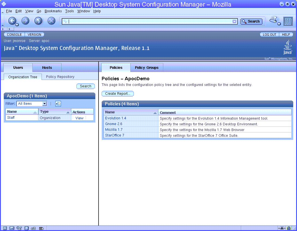
The Masthead provides a number of general links. The upper part of the Masthead contains the Utility Bar, which contains four links (from left to right):
-
The Console link returns you to the Java Web Console launch page.
-
The Version link opens a window that displays version information about the Configuration Manager.
-
The Log Out link logs you out of the Java Web Console, and thus the Configuration Manager, returning you to the Login page.
-
The Help link opens the online help pages.
The lower section of the Masthead contains:
-
The product name, Sun JavaTM Desktop System Configuration Manager, Release 1.1.
-
The name of the administrator currently logged in.
-
The server name.
-
The Sun Microsystems corporate logo.
Navigation Pane
Figure 2–2 Navigation Pane
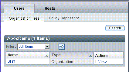
The Navigation pane allows the administrator, for both the user and host entity trees, to perform the following tasks:
-
Browse the entity trees.
-
Browse the policy repository.
-
Manage policy groups in policy repositories.
The Navigation pane contains two tab pages, Users and Hosts. These are discussed in more detail in the following sections.
Users Tab Page
The Users tab page provides the means to browse the organization tree and to manage policy groups for the organization tree. It has two sub-tabs: Organization Tree and Policy Repository.
Organization Tree Navigation
You can browse the organization tree using the parentage path or the Navigation table.
Parentage Path
At the top of the Users tab page is the parentage path, which is an area that shows the path to the current entity. Every path particle is a link that represents an entity, except for the last link, which is displayed as normal text and denotes the current entity.
To navigate using the parentage path, click on a link. This will refresh the Navigation pane so that the parentage path points to the clicked entity, and so that the navigation table contains the sub-entities of that entity. The Content pane with the configuration policy data associated with that entity is also refreshed.
Navigation Table
The navigation table is located below the parentage path, and lists the sub-entities of the current entity. The "Name" column contains the names of all sub-entities of the current entity. The "Type" column displays the type of the entity. The "Action" column contains a View link for every row.
If an entity is an organization or a role with sub-roles, you can click on the listed name, which results in the following actions:
-
Makes the selected sub-entity the current entity.
-
Refreshes the Navigation pane so that the parentage path points to the new current entity, and so that the navigation table contains the sub-entities of that entity.
-
Refreshes the Content pane with the configuration policy associated with that entity.
An entity can be either of type "Organization", "User" or "Role".
To view a listed entity's details without changing the current entity in the Navigation pane, click on the View link. This changes the background color of the selected row to blue and refreshes the Content pane with the data associated with the selected entity.
A row with blue background marks the entity whose data is currently visible in the Content pane.
The top of the navigation table contains the Filter drop-down
menu and the Advanced Filter icon. See Advanced Filter for more information. When the table contains more than ten
entries, the Page/Scroll Through All Data icon  appears,
which allows you to change the view of the table entries.
The Filter drop-down menu allows you to choose which type of entity to display in the navigation table. It contains the following choices:
-
"All Items" displays all types of entities in the navigation table.
-
"Organizations" displays only entities of type "Organization" in the navigation table.
-
"Users" displays only entities of type "User" in the navigation table.
-
"Roles" displays only entities of type "Role" in the navigation table.
Advanced Filter
Figure 2–3 Advanced Filter dialog
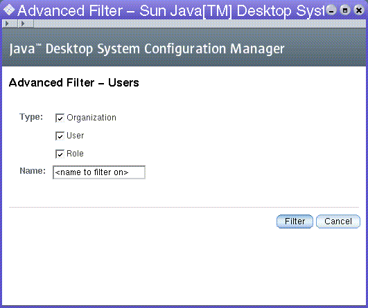
The Advanced Filter function enables the administrator to define the types of entities to be displayed.
 Using the Advanced Filter dialog
Steps
-
Click the Advanced Filter icon
 at
the top of the navigation table to open the dialog.
 -
In the Type section, select the type of entity that you want to filter. For a more specific filter, type a name in the Name text field.
Note –You can use an asterisk "*" in the Name text field as a wildcard.
-
Click the Filter button at the bottom of the dialog to run the filter.
Search
This function allows the administrator to search through the organization tree for certain entity types and entity names.
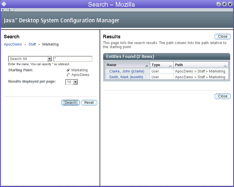
Figure 2–4 Search window
 Searching for an entity
Steps
-
Click the Search button in the Navigation pane.
The Search window opens. The window contains a masthead, a parameter area on the left, and a results area on the right. The parameter area displays the parentage path of the current entity at the top.
Note –If the Search button in the Navigation pane of the main window is clicked while the Search window is open in the background, the Search window becomes the topmost window. The current entity of the Search window, which is displayed by the parentage path in the parameter area of the Search window, is refreshed. All other parameters and the content of the result area are unchanged.
-
Select the desired entity type from the list box underneath the parentage path.
To search for a particular entity type, select that type from the drop-down list underneath the parentage path. The available selections are:
-
Search All
-
Search Organizations
-
Search Users
-
Search Roles
-
Search Domains
-
Search Hosts
-
-
To further refine category results, type a string into the search fields available for each category type.
The default value for the filter strings is *, indicating "all". The asterisk can be used within a string typed in a search field as a wildcard.
Note –The search function is not case-sensitive.
-
Select an option from the Starting Point section to determine the starting point of the search.
All selections begin a deep search of the organization tree. The difference lies in the starting point of the search. A search from the root begins at the top of the organization tree, a search from another location starts from that location in the tree.
Clicking on any path particle in the parentage path changes the current location for the search to the selected entity.
-
Select the number of results to be displayed from the Results to be displayed per page list box.
-
Click the Search button.
Once the search is complete, the results area displays a table containing the search results.
-
To start another search, or to clear current search parameters, click the Reset button in the parameter area.
Working with Search Results
Figure 2–5 Search results table
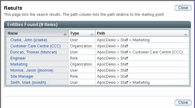
After performing a search, a result table appears in the results area of the Search window. The table contains three columns:
-
“Name” displays the name of the entity.
-
“Type” displays the type of the entity.
-
“Path” displays the path to the entity. The path is relative to the starting point of the search.
If the search was for an entity of type “User”, a fourth column, called “UserID” is visible on the result table.
Note –
You can sort results by clicking the arrow next to the appropriate column header. For instance, to sort by type, click the arrow next to the “Type” column.
To view a result, click on the corresponding name in the “Name” column. This brings the main Configuration Manager window to the foreground. The Content pane displays the configuration policy associated with that entity. The entity is also highlighted in blue in the Navigation pane.
Hosts Tab Page
Figure 2–6 Hosts tab page
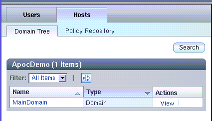
The configuration settings linked to the entities listed in the Hosts tab page are used for host-based configuration.
On the client side, the user-based configuration settings are fetched from the organization tree based on the username. The host-based configuration settings are fetched from the domain tree based on the IP or the host name of the host that the user is working on.
By offering configuration settings that are host-based, settings that depend on network environments can be easily configured. A typical scenario is the roaming user who has one user-based configuration but nevertheless can make use of the optimal proxy configuration depending on the host that the user is working is on.
The Hosts tab page contains two sub-tabs that are called Domain Tree and Policy Repository, respectively.
Domain Tree Tab Page
Figure 2–7 Domain Tree tab page
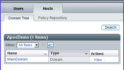
The domain tree displays the configuration settings for the host that the user is working on. It opens by default when the Hosts tab is clicked.
Navigation through the domain tree works in the same way as navigation through the organization tree. See Organization Tree Navigation for more information.
The action bar of the domain tree navigation table contains the Filter drop-down menu, with the following items:
-
“All Items” displays all types of entities.
-
“Domains” displays entities of type Domain.
-
“Hosts” displays entities of type Host.
The action bar also contains the Advanced Filter icon, described in Advanced Filter, Hosts Page.
Advanced Filter, Hosts Page
Figure 2–8 Advanced Filter window
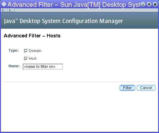
Clicking the Advanced Filter icon in the action bar of the domain tree navigation table opens the Advanced Filter window. It works in the same way as the advanced filter for the organization tree. See Advanced Filter. The advanced filter for the domain tree provides Domain and Host entity types to filter from.
Domain Tree Search
Figure 2–9 Domain Tree search window
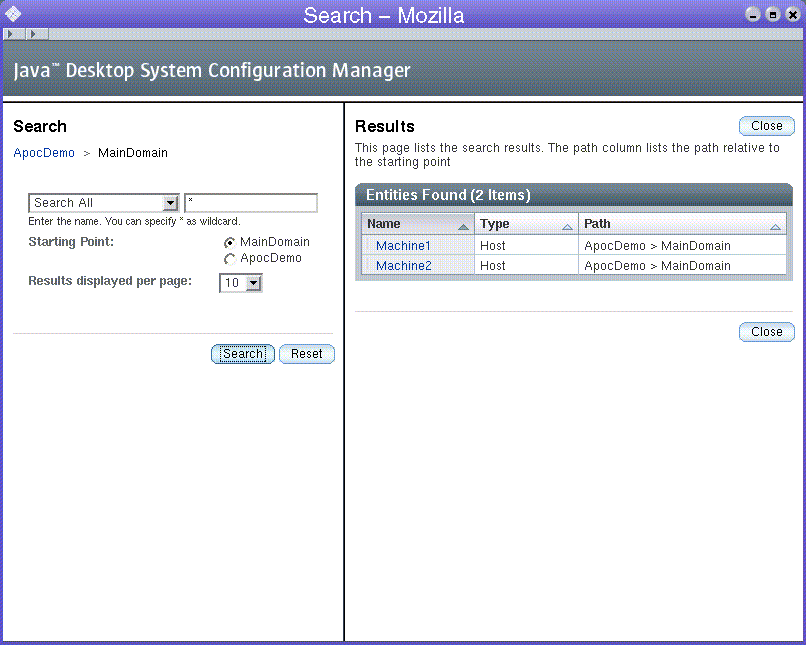
When you click on the Search button in the Domain Tree tab, the Domain Search window appears. The Domain Search operates in the same way as the search in the organization tree. See Search for more information.
Policy Repositories
Figure 2–10 Policy Repositories tab
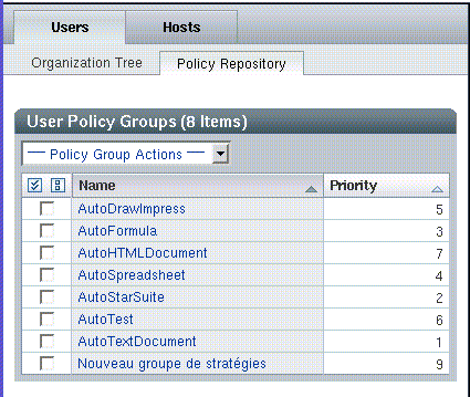
A Policy Repository tab exists under both the Users tab and under the Hosts tab.
A policy repository is a container for either user policy groups or host policy groups. The policy groups are organized in an ordered list. The sequence is defined by priorities.
Policy Group Table
The policy group table is located at the top of the page and lists the policy groups. The table contains three columns: a selection column, "Name", and "Priority". See Figure 2–10.
The selection column is used to mark the rows to which the actions listed in the Policy Group Action drop-down menu are applied.
Navigating Policy Groups
To navigate to a policy group, click on its name in the "Name" column. This will change the background color of the selected row to blue and refresh the Content pane with the data that is associated with the selected policy group.
The "Priority" column contains the priority of the policy group. The priority is used to define the merge order of the policy groups if an administrator has associated more than one policy group to an entity.
A row with blue background marks the policy group whose data is currently viewed in the Content pane .
Policy Group Action Bar
The Policy Group Actions drop-down menu contains the following actions:
Table 2–1 Policy Group actions|
Name |
Action |
|---|---|
|
New |
A dialog window opens, where the administrator enters the (unique) name of the policy group. After clicking OK, the policy group is added. The Navigation pane is refreshed to reflect the changes. |
|
Delete |
A pop-up window opens, with a warning message to confirm deletion of the policy group(s). If the administrator clicks OK, the policy group(s) are deleted. The Navigation pane is refreshed to reflect the changes. |
|
Rename |
A dialog window opens, the administrator enters the new (unique) name for the policy group, the policy group is renamed and the Navigation pane is refreshed to reflect the changes. |
|
Edit Priorities |
A dialog window opens, which contains a list box for changing the priorities. |
|
Export |
A dialog window opens. The administrator enters the destination path where the selected policy group(s) are exported to. |
|
Import |
A dialog window opens. The administrator selects the policy group(s) to be imported. After clicking OK, the policy group is added and the Navigation pane is refreshed to reflect the changes. |
Policy Group Priorities
The concept of policy group priorities allows you to define the order in which the layers are merged. The policy group priorities are used during merging if an entity has more than one policy group assigned. In this case, the hierarchy of entities is not sufficient to determine the sequence in which the policy groups are merged. This is solved by assigning priorities to policy groups.
To open the Policy Group Priorities dialog, select Edit Priorities from the Policy Group Actions drop-down menu.
Figure 2–11 Policy Group Priorities window
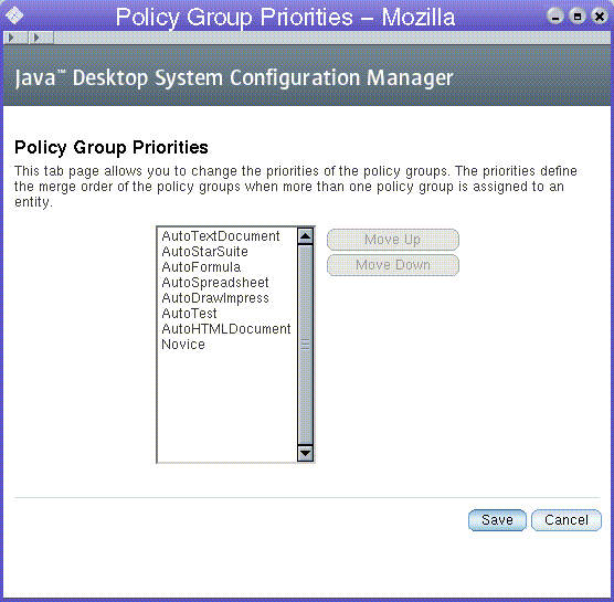
 To increase or decrease the priority of a policy group
Steps
-
Select the policy group from the list.
-
Click on the Move Up or Move Down button to increase/decrease the priority.
Content Pane
Figure 2–12 Content pane
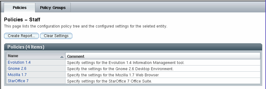
The Content pane displays the data associated with the selected entity or policy group in the Navigation pane. The data is grouped into tab pages, which are accessed by clicking the corresponding tab at the top of the Content pane. The selections made in the Navigation pane determine the number and type of tabs displayed in the Content pane.
The Policies tab page is the default active tab page. The currently active tab page stays active if selections are changed in the Navigation pane, as long as the selection made offers that tab page. If not, the Policies tab page becomes the active tab page. The internal state of a tab page (parentage path, sort order) is recalled when the tab page becomes active again.
Policies Tab Page
Figure 2–13 Policies tab page
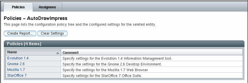
Use the Policies tab page to navigate the configuration policy tree, which displays subgroups, configuration settings, or both.
Every Policies page contains a Create Report button. This button allows access to the reporting functionality. See Reporting for more information.
If the Policies page contains a Policies table, a Clear Settings button is displayed. The Clear Settingsbutton deletes all of the configuration settings that are defined for the current policy of the selected entity, including the settings for the associated sub-policies. Clicking the Clear Settings button activates a warning dialog, which informs the administrator about the implications of this action.
Every root entry in the configuration policy tree denotes an application, for
example, Mozilla. The tree below the application organizes
the configuration settings that belong to that application.
Parentage Path
The parentage path is displayed at the top of the page underneath the tabs. It shows the current location in the configuration policy tree. It functions in the same way as the parentage path in the Navigation pane. See Parentage Path.
Policies Table
Figure 2–14 Policies table
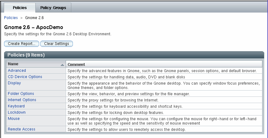
The Subgroups table is located below the parentage path. The table lists the subgroups of the current location in the configuration policy tree. It contains two columns: "Name" and "Comment".
The "Name" column contains the names of all subgroups of the current location in the configuration policy tree. The name is displayed as a link.
To navigate through the configuration policy tree, click on a name link. This refreshes the Content pane so that the parentage path points to the new location in the configuration policy tree, and refreshes the Content pane to display the Policies table.
The "Comment" column contains a short description of the subgroup.
Policies
Configuration settings for policies are displayed in the Policies page of the Content pane.
Figure 2–15 Policies page
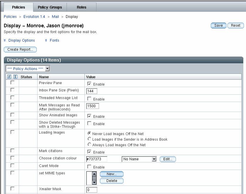
The data is presented in tables. The tables have four columns. A selection column that contains selection icons, a "Status" column, a "Name" column and a "Value" column. The action bar on the table has a drop-down actions menu.
 To perform an action on an element
Steps
-
Select the check box in the selection column of the desired element.
-
Select an action from the Policy Actions drop-down menu. The following table describes all actions
Action
Operation
Protect
Sets the selected element to be protected.
Unprotect
Removes the protection for the selected element.
Clear
Deletes the data that is stored in the element for the current entity.
Apply Default
Uses the default setting for the application.
To the left of an element name, two icons show the status of that element. The following table summarizes the icons and their function:
Icon
Meaning
Operation

This icon illustrates that the value of the element was set at this level of the organization tree.
-

This icon, which is also a link, illustrates that the value of the element was set at a higher level of the organization (or domain) tree. The value that the administrator sees is the result of the merging of layers, or entity levels, within the organization.
When you click on the icon, it navigates you to where the value was set.

This icon illustrates that the protection of the element was set at this level of the organization (or domain) tree. Protection is inherited through both the organization and configuration policy trees.
-

This icon, which is also a link, illustrates that the protection of the element was set at a higher level of the organization (or domain) tree. The protection of this element or item is as a result of merging of layers, or entity levels, within the organization.
Clicking on this icon navigates to the level where the protection was set.
Data values can be changed by changing the values in the "Value" column. Value changes as well as status changes must be saved. Saving is done by clicking on the Save button.
Sets
Figure 2–16 Adding a new property
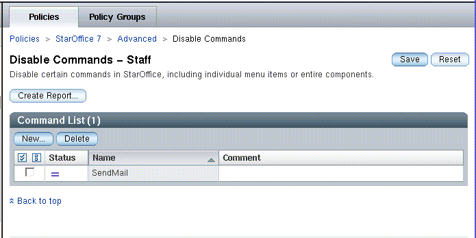
In general, the content and structure of the Policies tab page is static, thus the number of properties and sections for a certain subgroup is given and can not be modified by the administrator. This is sufficient for most of the administration tasks. However, some applications manage lists of items, where the administrator is able to add or remove items. Therefore, the Configuration Manager provides sets to offer a similar functionality. Sets allow administrators to add or remove properties during runtime.
 To add an element to a set
Steps
-
Click on the New button.
-
Enter the name of the new element in the dialog that appears.
The element is then added and the main window refreshed.
-
In the main window, the new element can be edited.
-
To make the changes permanent, it is necessary to explicitly click the Save button.
Deleting an element
To delete elements from a set, select the element and click the Delete button.
Note –
A set can also contain one or more sets. To edit a set, click the name of the set in the list.
Policy Groups Tab Page
Figure 2–17 Policy Groups tab page
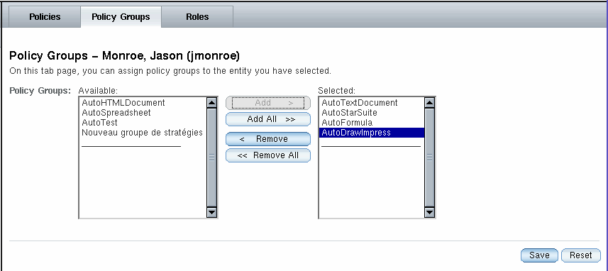
If an entity has been selected in the Navigation pane, the Content pane contains the Policy Groups tab page. It allows the administrator to add and remove policy groups to the selected entity.
The left list contains the available policy groups that are currently not assigned to the entity. The right list contains the policy groups currently assigned to the entity. By selecting one or more items the administrator can add and remove the policy groups to or from the entity.
Adding and Removing Policy Groups
 To add a policy group listed in the Available list
on the left side
Steps
-
Select one or more policy groups from the Available list that you want to add to the entity.
-
Click the Add button to add the selected policy group to the Selected list on the right side.
-
Click Save to store the new assignment.
 To remove a policy group from an entity
Steps
-
Select the policy group or groups from the Selected list that you want to remove from the entity.
-
Click the Remove button to remove the selected policy group.
-
Click Save to make the removal permanent.
Note –You can also click the Add All and Remove All buttons to add or remove all policy groups to or from the selected entity.
Assignees Tab Page
Figure 2–18 Assignees tab page
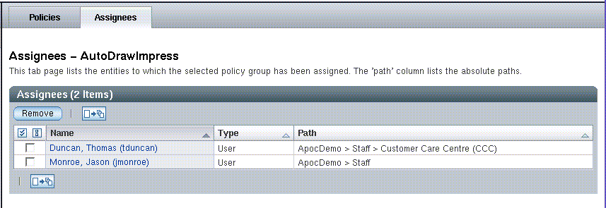
If a policy group is selected in the Policy Repository tab page of the Navigation pane, the Content pane contains the Assignees tab page. The Assignees page lists all entities that the selected policy group is assigned to.
The following actions can be performed on the Assignees tab page:
-
The Remove button breaks the association between the selected entity(s) and the policy group selected in the Navigation pane.
-
The selection column is used to select the rows to be removed.
-
Clicking on an entity in the "Name" column refreshes the Navigation pane, so that the clicked entity is the entity in the Navigation pane with the blue background.
-
The "Type" column displays the type of the entity. An entity can be either of type "Organization", "User"or "Role".
-
The "Path" column contains the path to the entity in the organization or domain tree.
Roles Tab Page
Figure 2–19 Roles tab page

If an entity of type "User" is selected in the Navigation pane, the Content pane contains the Roles tab page. The Roles tab page lists all the roles that the selected user is a member of.
This page has two columns "Name" and "Path". "Name" contains the names of the roles and "Path" contains the absolute path to the roles.
Users Tab Page
Figure 2–20 Users tab page

The Users tab page appears in the Content pane when a role is selected in the Navigation pane. The Users page lists all of the users that are members of the selected role.
The Users table has two columns: "Name" and "Path". The "Name" column contains the names of the users and the "Path" column contains the absolute path to that user. The absolute path is shown because it is possible that a role has members which may not be located below the current entity.
Reporting
A report is a read-only view of all configuration settings that contain data. A report is triggered by clicking the Create Report button. The Configure Report dialog then appears.
Figure 2–21 Configure Report dialog
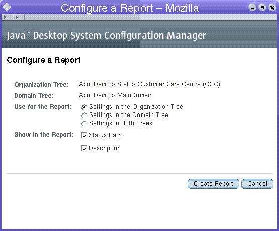
The Configure Report dialog allows you to customize the following:
-
Which tree (organization and/or domain tree) to use (Use for the Report section).
-
Which columns to show in the generated report (Status Path and Description can be disabled).
 Creating a Report
Steps
-
Click the Create Report button in the appropriate window of the Content pane.
The Configuration Report dialog appears.
-
Customize the settings for the following options:
-
The Organization Tree option contains the fully qualified path to the organization member (organization, user or role) currently selected in the navigation area.
-
The Domain Tree option contains the fully qualified path to the domain member (domain or host) currently selected in the navigation area.
-
Use the radio buttons in the Use for the Report section to specify the configuration settings to use in the report. The configuration settings of a member of the organization tree, the configuration settings of a member of the domain tree, or a combination of the two settings can be used. The main use for the latter case is to provide the administrator a way to list the configuration for user 'a' on machine 'b'. The default selection of the radio button group depends on the selected tab in the Navigation pane. If the Users tab page is open, the Settings in the Organization Tree choice is selected by default. Otherwise, if the Hosts tab page is open, the Settings in the Domain Tree choice is selected.
Note –If the administrator clicks the Create Report button while the configuration settings of a policy group are displayed in the Policies tab page in the Content pane, neither of the user interface elements listed in the paragraph above are displayed, because it makes no sense to generate a report for a policy group in combination with any other member. A report of a policy group always contains the configuration settings based on the selected policy group only.
-
The Status Path and the Description check boxes are used to toggle the display of the "Status Path" and "Description" columns in the report window.
-
-
Click the Create Report button to close the Configuration Report dialog.
Once customized, clicking on the report opens a read-only view of the selected data.
Report Window
The report window is a browser window optimized for easy saving and printing. As a consequence no images are used on the report page.
Figure 2–22 Report window
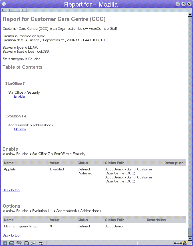
The main parts of a report are as follows:
-
The main header
-
The environment information
-
The table of contents
-
The tables containing the configuration settings
The main header contains the string "Report - " followed by the name(s) of the organization and domain members used to generate this report.
The environment information contain the organization/domain member used, the creator, the creation date, the back-end type, host and location, as well as the start subgroup.
The table of contents provides a condensed array of links which point to any table containing configuration settings in this report.
The tables containing the configuration settings are grouped in subgroups. Only subgroups that contain at least one configuration setting for the organization or domain member in question are listed. Every table has a title containing the name of the subgroup and the position of the subgroup. When applicable, a number represents the position of the subgroup. For each level an addition number is displayed. The value of each number represents the amount of subgroups that are listed for this level.
The table itself contains the following columns:
-
"Name" contains the name of the configuration setting.
-
"Value" contains the value of the configuration setting.
-
"Status" contains the status of the configuration setting. Possible values: "Defined", "Read-only", or both. "Defined" indicates that this configuration setting has value. "Read-only" denotes a configuration setting which cannot be changed in layers below. If a configuration setting has a value, it is always defined, but a configuration setting can be read—only without having a value.
-
"Status Path" (optional) contains the path where the status is set.
-
"Description" (optional) contains a short explanation of the configuration setting.
Odd table rows have a light background to enhance the readability. After each table, a Back to top link is displayed. Clicking on that link displays the table of contents again.
Logout
Click the Log Out link in the masthead to end the Configuration Manager session.
Help
Help is provided in three different ways:
-
The main help pages are accessed by clicking the Help link on the upper right side of the masthead. This opens a separate browser window.
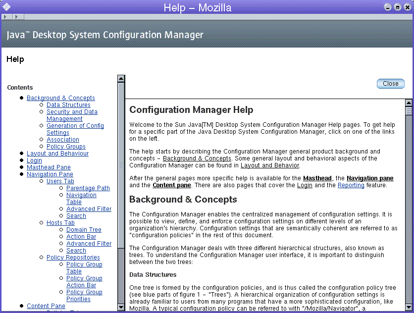
When navigating through the Content pane, the help facility is context sensitive. Clicking Help scrolls the help page to the section corresponding to the current tab page.
-
Inline help is provided, giving the administrator a short description of the particular item they are working on. The description can be seen at the top of each page.
Where necessary, inline help provides descriptions of configurable settings and the types of values they will accept.
-
Tool Tips are provided under all graphical images and links. To see the Tool Tip, leave the mouse over an image or link.
- © 2010, Oracle Corporation and/or its affiliates
