A P P E N D I X  A

Connector Pinouts

This appendix provides reference information about the Sun Fire X4170, X4270, and X4275 Servers back panel ports and pin assignments.

Topics covered in this appendix include:

For the locations of the back panel ports on the servers, see FIGURE 1-4 and FIGURE 1-5.


A.1 Serial Management Port Connector

The serial management connector (labeled SER MGT) is an RJ-45 connector located on the back panel. This port is the default connection to the system console.

FIGURE A-1 Serial Management Connector Diagram
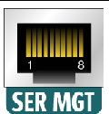

Figure showing serial management port.


Figure Legend

1

Request to Send

5

Ground

2

Data Terminal Ready

6

Receive Data

3

Transmit Data

7

Data Set Ready

4

Ground

8

Clear to Send


A.2 Network Management Port Connector

The network management connector (labeled NET MGT) is an RJ-45 connector located on the motherboard and can be accessed from the back panel. This port needs to be configured prior to its use.

FIGURE A-2 Network Management Connector Diagram


Figure showing network management port.


Figure Legend

1

Transmit Data +

5

Common Mode Termination

2

Transmit Data -

6

Receive Data -

3

Receive Data +

7

Common Mode Termination

4

Common Mode Termination

8

Common Mode Termination


A.3 Video Connector

The video connector (VGA) is an HD-15 connector that can be accessed from the back panel.

FIGURE A-3 Video Connector Diagram
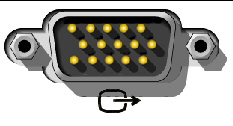

Figure showing the video port (VGA).


Figure Legend

1

Red Video

9

[KEY]

2

Green Video

10

Sync Ground

3

Blue Video

11

Monitor ID - Bit 1

4

Monitor ID - Bit 2

12

Monitor ID - Bit 0

5

Ground

13

Horizontal Sync

6

Red Ground

14

Vertical Sync

7

Green Ground

15

N/C (Reserved)

8

Blue Ground


A.4 USB Connectors

Two Universal Serial Bus (USB) ports are located on the motherboard and can be accessed from the server back panel.

FIGURE A-4 USB Connector Diagram


Figure showing USB connector ports.


Figure Legend

USB 0-1

+5 V (fused)

USB 1-1

+5 V (fused)

USB 0-2

USB0/1-

USB 1-2

USB2/3-

USB 0-3

USB0/1+

USB 1-3

USB2/3+

USB 0-4

Ground

USB 1-4

Ground


A.5 Gigabit-Ethernet Connectors

Four RJ-45 Gigabit-Ethernet connectors (NET0, NET1, NET2, NET3) are located on the system motherboard and can be accessed from the back panel. The Ethernet interfaces operate at 10 Mbit/sec, 100 Mbit/sec, and 1000 Mbit/sec.

FIGURE A-5 Gigabit Ethernet Connector Diagram


Figure showing Gigabit Ethernet port connector.[ D ]


Figure Legend

1

Transmit/Receive Data 0 +

5

Transmit/Receive Data 2 -

2

Transmit/Receive Data 0 -

6

Transmit/Receive Data 1 -

3

Transmit/Receive Data 1 +

7

Transmit/Receive Data 3 +

4

Transmit/Receive Data 2 +

8

Transmit/Receive Data 3 -