| C H A P T E R 2 |
|
ILOM Platform Features for the Sun Fire X4170, X4270, and X4275 Servers |
This chapter provides platform-specific information related to ILOM 3.0 running on the Sun Fire X4170, X4270, and X4275 Servers. For ILOM 3.0, the same additional platform-specific features are supported as were supported for ILOM 2.0. These features are described in this chapter.
The following topics are covered in this chapter:
| Note - The features described in this chapter are supported in addition to the common ILOM 3.0 features supported for all x64 servers. |
By default, you connect to the server’s service processor (SP) using the out-of-band network management port (NET MGT). The ILOM sideband management feature enables you to select either the NET MGT port or one of the server’s Gigabit Ethernet ports (NET 0, 1, 2, 3), which are in-band ports, to send and receive ILOM commands to and from the server SP. In-band ports are also called sideband ports.
The advantage of using a sideband management port to manage the server’s SP is that one less cable connection and one less network switch port is needed. In configurations where a great number of servers are being managed, such as data centers, sideband management can represent a significant savings in hardware and network utilization.
You can configure sideband management using either the web interface, the command-line interface (CLI), the BIOS, or IPMI. For special considerations and configuration instructions, see the following sections:
When sideband management is enabled in ILOM, the following conditions might occur:
| Note - If the ports are configured as switch ports and participate in the Spanning Tree Protocol (STP), you might experience longer outages due to spanning tree recalculation. |
|
1. Log in to the ILOM web interface.
2. Select Configuration -> Network.
The Network Settings page appears.
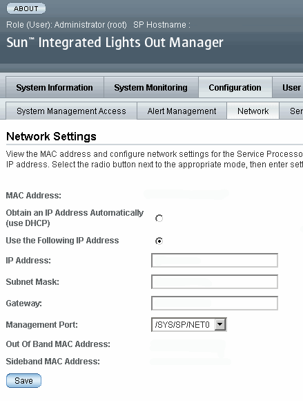
3. In the Network Settings page, do the following:
a. Select DHCP to acquire the IP address automatically or specify the appropriate IP address.
b. To select a sideband management port, click the Management Port drop-down list and select the desired management port.
The drop-down list enables you to change to any one of the four Gigabit Ethernet ports, /SYS/MB/NETn, where n is 0 to 3. The SP NET MGT port, /SYS/SP/NET0, is the default.
c. Click Save for the changes to take effect.
|
1. Log in to ILOM using the CLI.
| Note - Using a serial connection for this procedure eliminates the possibility of losing connectivity during sideband management configuration changes. |
2. If you logged in using the serial port, you can assign a static IP address.
For instructions, see “Use the Serial Connection to Change the ILOM SP IP Address” in the Sun Fire X4170, X4270, and X4275 Servers Installation Guide (820-5827).
3. To show the current port settings, type:
The network properties appear. For example:
In the above output the current active macaddress is the same as the SP’s outofbandmacaddress and the current active managementport is set to the default (/SYS/SP/NET0).
4. To set the SP management port to a sideband port, type the following commands:
-> set /SP/network pendingmanagementport=/SYS/MB/NETn
The network properties appear and show that the change has taken effect. For example:
In the above output the macaddress matches the sidebandmacaddress, and the managementport matches the pendingmanagementport.
|
You can access the BIOS Setup utility screens from the following interfaces:
To configure sideband management using the host BIOS Setup utility, perform the following steps:
1. Power on or power cycle the server.
2. To enter the BIOS Setup utility, press the F2 key while the system is performing the power-on self-test (POST).

When BIOS is started, the main BIOS Setup utility top-level screen appears. This screen provides seven menu options across the top of the screen.
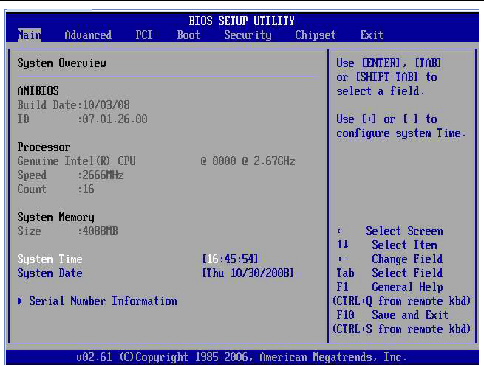
3. In the main screen, select Advanced --> IPMI Configuration.
The IPMI Configuration screen appears.
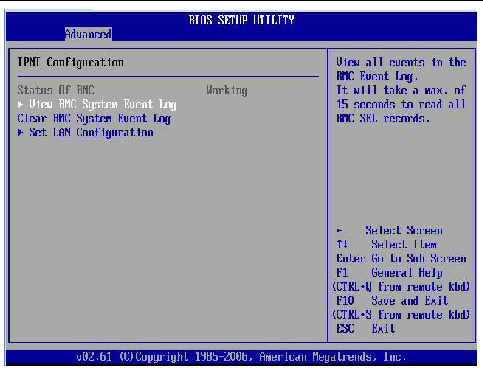
4. In the IPMI Configuration screen, select the Set LAN Configuration option.
The LAN Configuration screen appears.
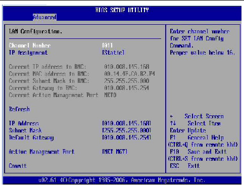
5. In the LAN Configuration screen, do the following:
a. Use the left and right keys to select the IP Assignment option and set it to DHCP.
b. Use the left and right keys to select the Active Management Port option and set the port to a sideband management port (NET0, NET1, NET2, NET3).
The NET MGT port is the default.
c. Select Commit for the change to take effect.
You can switch the serial port output of the Sun Fire X4170, X4270, and X4275 Servers between the SP console (SER MGT) and the host console (COM1). By default, the SP console is connected to the system serial port. This feature is beneficial for Windows kernel debugging, as it enables you to view non-ASCII character traffic from the host console.
You can switch serial port output using either the ILOM web interface or the ILOM command-line interface (CLI). For instructions, see the following sections:
|
To switch the serial port output using the ILOM web interface, perform the following steps:
1. Log in to the ILOM web interface.
2. In the ILOM web interface, select Configuration --> Serial Port.
The Serial Port Settings page appears.
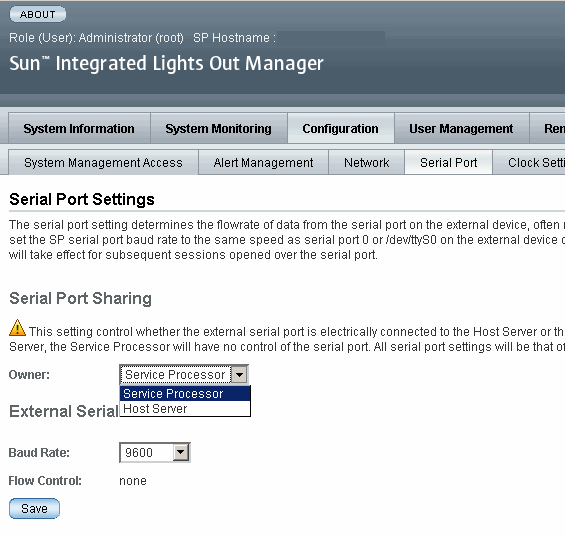
3. To select a serial port owner, click the Owner drop-down list and select the desired serial port owner.
The drop-down list enables you to select either Service Processor or Host Server.
By default, Service Processor is selected.
4. Click Save for your change to take effect.
|
2. To set the serial port owner, type:
-> set /SP/serial/portsharing/owner=host
When a server component fails, the server generates a component-specific fault that is captured by the ILOM SP. Some faults are cleared automatically when the failed component is replaced, but faults generated for components that are not hot-serviceable have to be cleared manually. You can use either the ILOM web interface or the command-line interface (CLI) to manually clear faults.
For the Sun Fire X4170, X4270, and X4275 Servers, the following types of faults must be cleared manually after the faulty component is replaced:
In addition, the following fault does not require replacement of a faulty part; however, user action is needed to clear it:
This fault is generated when the server’s top cover is removed while the AC power cords are still connected to the power supply, that is, power is not completely removed from the server.
When clearing faults, give consideration to the following:
The procedure for clearing a fault differs depending on the type of fault:
The /SYS/INTSW sensor and the /SYS/SP/SP_NEEDS_REBOOT sensor are asserted when the server’s top cover is removed while power is being applied to the server. This is an improper service action so these sensors serve to alert you to any unauthorized and inadvertent removal of the server’s cover. Thus, these sensors enable system administrators to have confidence that the physical integrity of the server has not been violated. This is particularly beneficial when the server is in a remote or uncontrolled location.
The /SYS/INTSW sensor is asserted when the chassis intrusion switch trips while the server is powered-on. If the AC power cords are connected to the server, power is being applied to the server. Even when you shut down the server’s host, power is still being applied to the server. The only way to remove power from the server completely is to disconnect the server’s AC power cords.
The chassis intrusion switch will trip if the server’s cover has been removed, the switch itself is misaligned, or the cover is not properly seated. This sensor is de-asserted when the integrity of the server’s chassis is restored, that is, when the removed cover is properly reinstalled returning the chassis intrusion switch to its closed state.
Like the /SYS/INTSW sensor, the /SYS/SP/SP_NEEDS_REBOOT sensor is asserted when the server’s chassis intrusion switch is tripped while power is being applied to the server. Shutting down the server’s host or shutting down the server by pressing the Power button does not shut down the SP because the SP continues to run when the server’s power is placed in Standby mode. The only way to remove power from the SP is to disconnect the AC power cords. To clear this sensor, you must replace the server’s cover and either reboot or power cycle the SP.
Assertion of the /SYS/SP/SP_NEEDS_REBOOT sensor indicates that the SP has been placed in a degraded mode of operation. In degraded more, ILOM stops taking DIMM inventory. This action is taken as a safety precaution because the SP has no way of knowing the real configuration of the server’s memory. For example, some of the DIMMs could have been removed while the server’s cover was improperly removed. To protect against such an occurrence, the SP is placed in the degraded mode.
TABLE 2-1 shows how the /SYS/INTSW sensor and the /SYS/SP/SP_NEEDS_REBOOT sensor work together to indicate the state of the server.
The server includes several of sensors that report on hardware conditions. Many of the sensor readings are used to adjust the fan speeds and perform other actions, such as illuminating LEDs and powering off the server.
This section describes the sensors that ILOM monitors for the Sun Fire X4170, X4270, and X4275 Servers.
The following types of sensors are described:
TABLE 2-2 describes the environmental sensors.
TABLE 2-3 describes the power supply fault sensors. In the table, n designates the numbers 0-1.
TABLE 2-4 describes the fan and security sensors. In the table, n designates numbers 0, 1, 2, etc.
|
This sensor tracks the state of the chassis intrusion switch. If the server’s top cover is opened while the AC power cords are still connected so that power is being applied to the server, this sensor asserts. If the top cover is subsequently replaced, this sensor is de-asserted. For more information, see Server Chassis Intrusion Sensors. |
||
|
This sensor asserts when the server’s cover is removed while the AC power cords are still connected so that power is being applied to the server. However, this sensor is not cleared by merely replacing the cover. This sensor indicates a server fault that must be cleared; otherwise, the SP will operate in a degraded mode. To clear this fault, replace the server’s top cover, power down the server’s host, and reboot the server’s SP. For more information, see Server Chassis Intrusion Sensors. |
TABLE 2-5 describes the power supply unit current, voltage, and power sensors. In the table, n designates numbers 0-1.
TABLE 2-6 describes the entity presence sensors. In the table, n designates numbers 0-n.
Copyright © 2009 Sun Microsystems, Inc. All rights reserved.