| Netra Data Plane Software Suite 2.1 Update 1 User’s Guide |
| C H A P T E R 11 |
|
Reference Applications |
This chapter describes Sun Netra DPS reference applications.
Reference applications illustrate how users applications are written to exploit full capability of Sun Netra DPS running on chip multithread architecture. Each reference application consists of extensive examples. In many cases, these examples can be leveraged as building blocks of the users deployment application.
The IP Packet Forwarding Application (ipfwd) performs IPv4 (Internet Protocol Version 4) and IPv6 (Internet Protocol Version 6) forwarding operations. When packet traffic is received, the application performs forwarding table searches and determines the destination (next hop). It then re-writes the packet header of the packet to be forwarded.
The basic IP Forwarding application consists of three or more software threads forming a traffic flow with multiple traffic flow running in parallel. The following figure depicts the basic IP Forwarding structure.
FIGURE 11-1 IP Forwarding Traffic Flows

The receive thread performs the following tasks:
1. Polls packets received from a particular DMA channel’s HW descriptor ring.
2. Checks for received packet status.
3. Delivers the packet to the forwarding thread through fast queue.
The bulk of implementation of the receive thread resides in the device driver. Normally, no user modification is required.
The forward thread performs the following tasks:
1. Polls packet from Rx fast queue enqueued by Rx thread.
2. Verifies the packet header.
3. Checks the received packet’s integrity.
4. Encapsulates or decapsulate packet header, if necessary.
5. If the packet is destined to host, forwards the packet to the host. Otherwise, performs lookup for next hop information, based on a selected lookup algorithms, such as:
6. Updates the packet header with next hop’s address.
7. Delivers the packet to the Tx thread through fast queue.
You can form single or multiple threads in a pipeline depending on the workload of the forwarding tasks.
The transmit thread performs the following tasks:
1. Polls packet from IP forwarding thread through fast queue.
2. Posts the packet to the target transmit descriptor ring of the Tx DMA channel.
Similar to the receive thread, the majority of the code of the transmit thread resides in the device driver.
In this reference application, each software thread is mapped into a hardware CPU strand. The hardware classifier and the hashing mechanism spread ingress traffic into multiple parallel traffic flows, each implemented in a multiple threads pipeline described above. Multiple traffic flows can run in parallel. The overall forwarding packet rate is the aggregate packet rate of each traffic flow.
All ipfwd source files are located in the following directories:
user_workspace/SUNWndps/src/apps/ipfwd
|
1. Copy the ipfwd reference application from the SUNWndps/src/apps/ipfwd directory to a desired directory location.
2. Execute the build script in the ipfwd directory.
./build cmt type [ldoms [diffserv] [acl] [gdb] [excp] [tipc] [no_freeq] [gre] [ipv6]] [profiler] [2port] [vnet] -hash POLICY_NAME
| Note - cmt (processor type) and type (network interface type) must be specified in each build. |
The build script supports the following arguments:
Specifies whether to build the ipfwd application to run on the CMT1 (UltraSPARC T1) platform or CMT2 (UltraSPARC T2) platform.
Specifies whether to build the ipfwd application to run on the logical domain environment. When this flag is specified, the IP forwarding logical domain reference application will be compiled. If this argument is not specified, then the non-logical domains (standalone) application will be compiled. Note that the options under the ldoms parameter (such as diffserv, acl, and gdb) can be enabled only when this option is specified. See How Do I Calculate the Base PA Address for NIU or Logical Domains to Use with the tnsmctl Command?.
Enables the differentiated services reference application.
Enables the access control list (ACL) reference application.
Enables gdb support in the logical domain environment.
Enables processing of IPv4 protocol exceptions and support of address resolution protocol (ARP).
Enables application to use TIPC to communicate with control plane application.
Enables IPv6 packet forwarding. Note that when this option is not specified, the application performs IPv4 forwarding.
Disables the use of free queues. Can be used with the diffserv option in an logical domain environment.
Enables the GRE reference application.
Generates code with profiling enabled.
Compiles dual ports on the 10-Gbps Ethernet or the UltraSPARC T2 NIU.
Enables the usage of vnet interfaces for exception handling by the ipfwd Sun Netra DPS application.
Enables flow policies. For more information, see Other IP Forwarder Options.
|
 In /src/sys/lwrte/apps/ipfwd, pick the correct build script, and run it.
For example, to build for 10-Gbps Ethernet on a Sun Netra or Sun Fire T2000 system, type:
In this example, the build script with the 10g option is used to build the IP forwarding application to run on the 10-Gbps Ethernet. The cmt argument is specified as cmt1 to build the application to run on UltraSPARC T1-based Sun Netra or Sun Fire T2000 systems.
|
1. Copy the binary into the /tftpboot directory of the tftpboot server.
2. On the tftpboot server, type:
3. At the ok prompt on the target machine, type:
| Note - network-device is an OpenBoot PROM alias corresponding to the physical path of the network. |
The following table shows the default system configuration.
The main files that control the default system configuration are:
The following table shows the default ipfwd application configuration.
The main files that control the ipfwd application configuration are:
Other IP forwarding application options can be enabled during the compile time by enabling them in the makefiles.
This option is used to bypass the ipfwd operation (that is, receive -> transmit without forwarding operation), uncomment the following line from Makefile.nxge to compile for the Sun multithreaded 10-Gbps NIU, 10-Gbps PCIe Ethernet adapter, and quad
1-Gbps PCIe Ethernet adapter.
When this option is enabled, the output destination port is determined by the output of the forwarding table lookup. Otherwise, the output destination port is the same as the input port. To enable this option, uncomment the following line from Makefile.nxge to compile for the Sun multithreaded 10-Gbps Ethernet, respectively:
This option is enabled by default. You must disable this flag when running Sun Netra DPS on UltraSPARC T2 version 2.2 and above for optimal performance.
This option enables the device driver to collect statistical information. To enable this option, uncomment the following line from Makefile.nxge. Note that there is a slight performance reduction when this option is enabled:
This option enables the IP forwarding application to display statistical information to the console. This option must be accompanied by the KSTAT_ON option. To enable this option, uncomment the following line from Makefile.nxge:
The default memory pool configuration of the IP forwarding application is one memory pool per traffic flow. This option overrides the default memory pool configuration. When this option is enabled, all traffic flows share one memory pool. To enable this option, uncomment the following line from Makefile.nxge:
This option enables the TIPC stack in ipfwd reference application to be configured using the Linux tn-tipc-config tool. The Linux tn-tipc-config tool uses vnet for exchanging commands/data. When the Linux tn-tipc-config tool is used, then the ipfwd reference application must be compiled with the -DTIPC_VNET_CONFIG flag enabled in the makefiles (for example Makefile.nxge):
When IP Forwarding is configured as cross configuration, the IPFWD_STATIC_CROSS_CONFIG flag must be enabled. The following is one example of cross configuration:
Port0 ---> Port1
Port1 ---> Port0
Specify a policy for spreading traffic into multiple DMA flows by hardware hashing. TABLE 11-2 describes each policy:
To enable one of the above policies, use the -hash option.
If none of the policies listed in TABLE 11-2 are specified, a default policy is given. The default policy is set to HASH_ALL. When you use the default policy, all L2, L3, and L4 header fields are used for spreading traffic.
The ipfwd_config.c file assists you in mapping application tasks to CPU core and hardware strands. Normally, mapping is set in the ipfwd_map.c file in the config directory. This configuration file is a productivity tool. This file provides a way to facilitate mapping in a quick manner without any modification to the ipfwd_map.c file.
This configuration file is not a replacement of ipfwd_hwarch.c, ipfwd_swarch.c, and ipfwd_map.c. This framework is to conduct performance analysis and measurement with different system configurations. The default (*_def) configurations specified assumes a minimum of 16 threads of the system allocated for Sun Netra DPS in ipfwd_map.c and all memory pool resources required are declared in ipfwd_swarch.c. You still need to specify system resources declarations and mapping in ipfwd_hwarch.c, ipfwd_swarch.c, and ipfwd_map.c. The configuration is assigned to a pointer named ipfwd_thread_config.
| Note - You can by-pass this file entirely and perform all the mapping in ipfwd_map.c. In this case, you would also need to modify ipfwd.c so that it does not interpret the contents of this file. |
Each application configuration is represented in an array of a six-element entry. Each entry (each row) represents a software task and its corresponding resources:
Strand number of the hardware strand (0 to 31 on an UltraSPARC T1 system and 0 to 63 on an UltraSPARC T2 system) on which this software task is to be run.
If zero, it indicates no Ethernet port needs to be opened when this task is activated. If non-zero, it indicates Ethernet port (port number specified by port#) needs to be opened. The contents of OPEN_OP consists of vendor and device ID as:
This is the port number of the Ethernet port to be opened. port# should match the physical port number displayed on the console when the boot command (with -v option used) is executed to perform tftpboot of the binary. For example, use the port# if the network device you would like to use for IP forwarding shows up as the following in the console output during boot:
In this case, the port number specified in the port# field of the application configuration should be set to 4.
If this is a multi-channel device (such as Sun multithreaded 10-Gbps Ethernet with NIU), this entry indicates the channel number within each port. Sun multithreaded 10-Gbps Ethernet device has 24 transmit channels (0 to 23) and 16 receive channels (0 to 16) in each port. Sun multithreaded 10-Gbps Ethernet with NIU has 16 channels (both tx and rx) in each port.
This is the role of the software task.
TROLE_ETH_NETIF_RX (performs a receive function)
TROLE_ETH_NETIF_TX (performs a transmit function
TROLE_APP_IPFWD (performs IP forwarding function)
See common.h for all definitions. If you do not want to run any software task on this hardware strand, the role field should be set to -1. By default, during initialization of the ipfwd application, the hardware strand that encounters a -1 software role is parked.
| Note - A parked strand is a strand that does not consume any pipeline cycles (an inactive strand). |
This is the identity of the memory pool. Note that in this reference application, each Ethernet port has its own memory pool. Each channel within each port has its own memory pool. Memory pools are declared in ipfwd_swarch.c.
The IP forwarding application can be set up in two different environments: standalone and logical domain.
In the standalone environment, Sun Netra DPS gains control of the entire system. All system resources are dedicated for Data Plane usage. When the ldoms option is not specified in the build script, then the ipfwd application is built for running on the standalone environment. In the standalone environment, no forward information base (FIB) is specified.
All packets are forwarded based on hard-coded information in the program. the users must modify the program to change the default forwarding information and its corresponding forwarding path. Using the IP forwarding application build script without specifying the ldoms option will generate the executable for the standalone environment.
In a logical domain environment, Sun Netra DPS and other logical domains share the system resources. Sun Netra DPS is used as the data plane, other logical domains are used as the control plane. The ipfwd application must be built with the ldoms option for this environment. The logical domain environment has more flexibility over the standalone environment on controlling the forwarding information and specifying the forwarding path.
The forwarding application consists of two major groups of components: data plane components that run on the Sun Netra DPS runtime and the control plane components and utilities that run on the Oracle Solaris OS.
The forwarding application fast path code are reside mainly in the following subdirectories:
The hardware architecture is identical to the default architecture in all other reference applications.
The software architecture differs from other applications in that it contains code for the specific number of strands that the target logical domain will have. Also, the memory pools used in the malloc() and free() implementation for the logical domain and IPC frameworks are declared here.
The mapping file contains a mapping for each strand of the target logical domain.
The rx.c and tx.c files contain simple functions that use the Ethernet driver to receive and transmit a packet, respectively.
ldc_malloc.c contains the implementation of the memory allocation algorithm. The corresponding header file, ldc_malloc_config.h, contains some configuration for the memory pools used.
user_common.c contains the memory allocation provided for the Ethernet driver, as well as the definition for the queues used to communicate between the strands. The corresponding header file, user_common.h, contains function prototypes for the routines used in the application, as well as declarations for the common data structures.
ipfwd.c contains the definition of the functions that are run on the different strands. In this version of the application, all strands start the _main() function. Based on the thread IDs, the _main() function calls the respective functions for rx, tx, forwarding, a thread for IPC, the cli, and statistics gathering.
The IP forwarder state machine implementation code resides in the following files and their corresponding header files:
ipfwd_config.c, and its header file, consists of default configuration entries that determine how application threads are mapped into hardware CPU strands for the forwarding application. In the ipfwd application, all software thread entry points (except the fast path manager) are mapped into the _main entry point (see ipfwd_map.c). In the _main() function, each thread is further assigned a particular task to perform based on the information specified in the file.
init.c contains the initialization code for the application. First, the queues are initialized. Initialization of the Ethernet interfaces is left to the rx strands, but the tx strands must wait until that initialization is done before they can proceed.
ipfwd_ipc.c contains the IPC logical domain framework initialization functions. The initialization of the logical domain framework is accomplished using calls to the functions mach_descrip_init(), lwrte_cnex_init(), and lwrte_init_ldc(). After this initialization, the IPC framework is initialized by a call of tnipc_init(). The previous four functions must be called in this specific order. The data structures are then initialized for the forwarding tables.
ipfwd_tipc.c, and its header files, contains the TIPC logical domain functions. When you specify the tipc option during the build, TIPC will be used as the communication protocol between control and data plane. Otherwise, IPC will be used by default.
ipv4_excp.c, and its header files, consists of code that handles exceptions, such as IP fragmentation and re-assembly.
ipfwd_flow.c, and its header files, specifies the L3/L4 classification flow entries. When TCAM_CLASSIFY is used in the -hash option during the build, these entries will be programmed into the TCAM during initialization of the application.
The diffserv/ directory consists of the diffserv implementation.
The gre/ directory consists of the GRE tunneling implementation.
The radix/ directory consists of the radix forwarding algorithm implementation.
To deploy the application, the image must be copied to a tftp server. The image can then be booted using a network boot from either one of the Ethernet ports, or from a virtual network interface. After booting the application, the IPC channels are initialized. After the IPC or TIPC channels are up, you can use the Oracle Solaris OS control plane utilities to set up the network interface, to manipulate the forwarding tables, and to gather statistics.
The code for the Oracle Solaris control plane components and utilities are located in the src/solaris subdirectory. This file implements a simple CLI to control the forwarding application running in the Sun Netra DPS runtime (LWRTE) domain. These applications are not built when ipfwd is built. They must be built separately using gmake in the directory and deployed into a domain that has an IPC channel to the LWRTE domain established.
The code for the Linux control plane components and utilities are located in src/linux. The applications for Linux are not built when ipfwd is built. They must be built separately using the makefile in src/linux and deployed into a domain that is running Linux. By default, the makefile in src/linux uses gcc version 4.3.2 which is a part of Wind River Linux Sourcery G++ 4.3-85 toolchain. The compiler is a cross-compiler for UltraSPARC T2 platform that is installed on a Linux/x86-64 machine.
The ifctl interface is used to configure interfaces of the Sun Netra DPS ipfwd application, as well as displaying the interface parameters. It is similar to the ifconfig utility in the Oracle Solaris OS, but the available commands and parameters provide the basic functionality only.
The following shows the usage of the ifctl tool:
ifctl iface-name port-num address tun [tunnel-address] tuntype 4in4|4in6|6in4|6in6|gre|none up|down netmask [netmask] mtu [mtu] vtag [vid]
Starting the tool without any options will display the current interfaces along with their configuration.
Gives a brief description of the command syntax.
Specifies the name of the interface. The first non-numeric string on the command line is interpreted as interface name, except the valid command words (up or down). The interface name can be up to 5 characters long.
Specifies the Ethernet port number assigned to the interface. The port number should always starts from 0.
Specifies the IP address to be assigned to the interface. The ifctl tool accepts IPv4 and IPv6 addresses in the following formats:
D.D.D.D (where D is a octet in decimal format)
H:H:H:H:H:H:H:H (where H is a 16 bit value in hex). ifctl supports the simplified forms of the IPv6 address string representations. The following formats are accepted:
Specifies the IP address of the remote end of the tunnel.
Specifies the type of the tunnel configured on the interface. The types of tunnels supported are:
Activate the interface. If the interface has been added previously and brought down subsequently, then the interface can be brought up without specifying the parameters again. This option must be used when adding the interface for the first time.
Shuts down the interface. All packets received on or forwarded to this interface will be dropped.
Configures the MTU of the interface. The value supplied is in bytes. It must be between 46 bytes and 1500 bytes. For interfaces that have tunneling enabled, the value represents the maximum L3 packet size, excluding the encapsulating headers, but including the payload L3 header.
Configures the netmask for the IPv4 interface. The netmask supplied must be in dotted decimal format.
Configures the VLAN ID (VID) of the interface. To disable VLAN tagging on an interface, provide a value of 0 for the VLAN ID using this option.
This section contains examples that show how to use the ifctl options.
Execute the following command:
Execute the following command:
Execute the following command:
Execute the following command:
Execute the following command:
Execute the following command:
|
|
Execute the following command:
|
|
Execute the following command:
|
|
Execute the following command:
Execute the following command:
Execute the following command:
Execute the following command:
The FIB Control utility (fibctl) is used to download the FIB table data from the control plane to the data plane. When fibctl is started in the control plane, the fibctl> prompt will appear. The program offers the following commands:
Connects to the channel with ID Channel_ID. The forwarding application is hard coded to use channel ID 4. The IPC type is hard coded on both sides. This command must be issued before any of the other command.
Loads an FIB table file that consists of FIB table data. The IP Forwarding Reference Application uses the following FIB table data file with the application:
SUNWndps/src/apps/ipfwd/src/solaris/fibctl_tables
Transmits the table with the indicated ID to the forwarding application. There are two simple predefined tables in the fibctl application.
Instructs the forwarding application to use the specified table. In the current code, the table ID must be 0 or 1, corresponding to predefined tables. Before a table can be used, it must be transmitted using the write-table command described above.
Requests statistics from the forwarding application and displays them.
Reads an IPC message that has been received from the forwarding application. Currently not used.
Issues the TNIPC_IOC_CH_STATUS ioctl.
Contains program help information.
1. Execute the appropriate gmake command.
a. To use the fibctl and ifctl utilities on an Oracle Solaris OS logical domain, execute the gmake in the Oracle Solaris OS subtree (SUNWndps/src/apps/ipfwd/src/solaris):
2. Execute the appropriate make command.
a. To use the fibctl and ifctl utilities on a Linux OS logical domain, copy the sources in src/linux and src/common onto a machine that has the cross-compiler installed.
For all utilities built for Linux logical domains, the TIPC=on option must be used.
b. In the linux directory, execute the make command.
c. On the system that has the cross-compiler installed, perform the following:
% mkdir ipfwd-utilities % cp ipfwd-utils.tar ipfwd-utilities % cd ipfwd-utilities % tar -xvf ipfwd-utils.tar % cd linux % make ifctl TIPC=on % make fibctl TIPC=on |
After the channel to be used is initialized using tnsmctl (must be channel ID 4 which is hard coded into the ipfwd application), use fibctl to change the behavior of ipfwd as shown below example:
fibctl> connect 4 fibctl> load fibctl_tables fibctl> write-table 0 fibctl> write-table 1 fibctl> use-table 0 fibctl> use-table 1 fibctl> quit |
The excpd application is responsible for:
To build the excpd application, the application source is provided with the Sun Netra DPS ipfwd reference application. The application source is present in the ipfwd/src/solaris/excpd directory. The following build options are provided:
./build lwip|sol [tipc]
| Note - The excpd application is not used when ipfwd reference application is used with Linux guest logical domain. |
The IPv4 packet forwarder with exception handling consists of:
ARP (RFC 826) is a protocol that enables dynamic mapping of IPv4 addresses to Ethernet addresses. It is used with the IPv4 forwarding application to map the next-hop IPv4 addresses in the FIB table to their Ethernet addresses.
The IPv4 exception handling enables fragmentation of egress packets and reassembly of fragmented packets that are destined to the local host.
FIB table management enables the updates of the next-hop IP addresses in the Data Plane FIB table, with their Ethernet addresses. When new Ethernet addresses are learnt, the FIB entries are updated by the FIB management layer and passed to the Data Plane application. When the exception handling is handled in control plane host using vnet for packet transfers, the FIB entries are updated by the learning module within the data plane application itself.
Exception handling is enabled only when the ipfwd application is built with the ldoms and excp options (see IP Packet Forwarding Reference Applications for an explanation of these build options).
The ipfwd reference application is extended with a framework that allows handling of ARP and IPv4 protocol exceptions. FIGURE 11-2 depicts the exception handling framework in the ipfwd application that use either LwIP or Solaris Host (TIPC/TNIPC) methods. FIGURE 11-3 depicts the exception handling frame framework that uses Oracle Solaris or Linux Host with vnet for packet transfers.
Three methods of ARP processing are provided in the ipfwd reference application when Oracle Solaris OS is used in the control plane logical domain. One method uses the lwIP ARP protocol layer to process ARP packets and to maintain the ARP cache. Another method uses the Oracle Solaris ARP layer to process ARP packets and to maintain the ARP cache, but uses either TNIPC or TIPC for packet transfers with the Oracle Solaris OS logical domain. A third method uses the Oracle Solaris ARP layer to process ARP packets and to maintain the ARP cache, but uses vnet interfaces for packet transfers with the Oracle Solaris OS logical domain.
When Linux OS is used in the control plane logical domain, only one method of ARP processing is provided. The Linux ARP layer is used to process ARP packets and to maintain the ARP cache. The vnet interfaces are used for packet transfers with the Linux OS logical domain.
When the lwIP ARP layer is used for ARP processing, the ARP layer is a part of the excpd application. lwIP is a static library that implements the TCP/IP protocol stack. The excpd application uses the ARP layer of lwIP to process the ARP packets and for ARP table maintenance.
In this method, the ARP layer in the Oracle Solaris OS control plane is used for ARP processing. The ARP cache is also managed in the Oracle Solaris OS. The excpd application is responsible only for FIB management. A STREAMS module named lwmodarp is used in the Oracle Solaris OS to interface with the Oracle Solaris ARP layer. For each interface enabled in the data plane, a corresponding vnet interface is configured in the Oracle Solaris domain. The lwmodarp module is inserted into the ARP-device STREAM of each configured vnet interface. This module communicates with the data plane application to receive and transmit ARP packets over IPC/TIPC.
In this method, the ARP layer in the Oracle Solaris OS or Linux OS is used for ARP processing. The ARP cache is also managed in the Oracle Solaris or Linux OS. The differences from the previous method are:
1. This method does not use TNIPC or TIPC for packet transfers with the control plane OS
2. This method does not use excpd, lwip, or lwmodarp modules
The FIB management is done in the ipfwd Sun Netra DPS application. The FIB table is pushed to the data plane using fibctl tool. The ipfwd application in Sun Netra DPS will learn the MAC addresses from ARP packets received from external hosts and from ARP packets that are transmitted from the control plane to external hosts. The learnt MAC addresses are used to update the FIB table that is currently in use.
IPv4 protocol exception handling involves fragmentation, reassembly, and local delivery. This section contains descriptions of these handling processes.
When a packet that must be forwarded needs to be fragmented, the IPv4 forwarder thread passes the packet to the fastpath manager thread. The fastpath manager thread calls the IPv4 fragmentation routine that fragments the packet. The fragments are then sent to the transmit threads of the outgoing interface.
When a packet is received in the data plane, the data plane IPv4 layer determines if the packet is destined to one of the configured local interfaces. If true, then the packet is passed to the fastpath manager that sends the packet to the IPv4 layer of the Oracle Solaris control domain. If such packets are fragments, then the Oracle Solaris IPv4 layer handles the reassembly. A STREAMS module named lwmodip4 is used in the Oracle Solaris OS to interface with the Oracle Solaris IPv4 layer. For each interface enabled in the data plane, a corresponding vnet interface is configured in the Oracle Solaris domain. The lwmodip4 module is inserted into the ARP-IP-device STREAM of each configured vnet interface. This module communicates with the data plane application to receive and transmit IPv4 packets over IPC/TIPC.
When a packet is received in the data plane, the data plane IPv4 layer determines if the packet is destined to one of the configured local interfaces. If true, then the packet is passed to the fastpath manager that sends the packet to the IPv4 layer of the Oracle Solaris OS or Linux control domain using one of the vnet interfaces in Sun Netra DPS that is connected to a vnet interface in the Oracle Solaris OS or Linux OS logical domain. If such packets are fragments, then the Oracle Solaris OS or Linux IPv4 layer does the reassembly of the fragments. Note that when vnet is used to transfer IPv4 protocol exception packets, lwmodip4 is not used in the Oracle Solaris OS and Linux OS logical domain.
FIB management is performed by the excpd application. The excpd application receives FIB tables from the fibctl utility. When a FIB table is received, the excpd application performs ARP cache lookup for the next-hop IP addresses in the FIB. It fills the MAC addresses in the FIB entries and transfers the completed FIB entries to the data plane. For FIB entries whose MAC addresses are not found in the ARP cache, it monitors the ARP cache until the MAC addresses are found.
FIGURE 11-2 Internal Block Diagram for the ipfwd Reference Application Using IwIP or Oracle Solaris OS Host With TIPC and TNIPC
FIGURE 11-3 Internal Block Diagram for the ipfwd Reference Application Using Oracle Solaris OS or Linux Host With vnet

FIGURE 11-2 depicts the exception handling framework in the ipfwd reference application that use either IwIP or Oracle Solaris OS Host (TIPC and TNIPC) methods. The boxes in gray and the arrows in green and red illustrate the exception path framework.
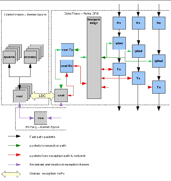
FIGURE 11-3 depicts the exception handling framework in the ipfwd reference application that use either Oracle Solaris OS host or Linux host using vnet. The boxes in gray and the arrows in green and red illustrate the exception path framework.
When exception handling is done in the control plane Oracle Solaris OS or Linux OS using vnet for packet transfers, FIB management is done in the data plane application itself. The FIB is pushed by the user using the fibctl tool. When ARP packets are received by the data plane application, either from external hosts (on fast path Ethernet interfaces) or from the control plane (on vnet interfaces), the data plane learns MAC addresses of the hosts. The learnt addresses are used to update the MAC addresses of the FIB table entries.
The exception path framework consists of the following components:
The IPv4 forwarder receives Ethernet frames from the Rx strand. The forwarder checks if the frames received contain IPv4 packets. All frames that do not contain IPv4 packets are passed to the fastpath manager (green arrows).
All frames that contain IPv4 packets are further processed by the IPv4 forwarder thread. While processing the IPv4 packets, if any IPv4 protocol exception is detected, the IPv4 forwarder thread passes those packets to the fastpath manager thread for processing the exception (green arrows).
The following IPv4 protocol exceptions will result in an exception condition:
The excpd application is a user-space Oracle Solaris OS application that is responsible for:
| Note - When ARP is processed in the Oracle Solaris OS or Linux OS using vnet for ARP packet transfer, the excpd exception application must not be used. |
lwIP is a static library that implements the TCP/IP protocol stack. This is used when ARP processing is done in excpd application. To use the lwIP ARP layer, the excpd application is built with the lwip option (see To Build the excpd Application When lwIP ARP Is Used With IPC).
This is used when ARP processing is done in the control domain Oracle Solaris ARP layer. This module is used to pass ARP packets between the Oracle Solaris ARP layer and the data plane ipfwd application. It uses IPC or TIPC to communicate with the data plane application.
| Note - When ARP is processed in the Oracle Solaris OS, the lwIP ARP layer is not used in the excpd application. The excpd application must be compiled with the sol option (see To Build the excpd Application When lwIP ARP Is Used With IPC). |
| Note - When the lwIP ARP layer is used, the lwmodarp module must not be used. |
| Note - When ARP is processed in the Oracle Solaris OS or Linux OS using vnet for ARP packet transfer, lwmodarp must not be used. |
This module is used for the processing of IPv4 packets that are destined to the local interfaces. The module passes IPv4 packets to and from the control plane Oracle Solaris IPv4 layer and the data plane ipfwd application. It uses IPC or TIPC to communicate with the data plane application.
| Note - This module must not used when IPv4 exception handling is done in the Oracle Solaris OS or Linux OS using vnet for packet transfer. |
The fastpath manager performs the following functions related to IPv4 exception handling and ARP processing:
The following tools are required to use the ipfwd application with exception handling and ARP handling.
See Control Plane Components and Utilities.
See Control Plane Components and Utilities.
The insarp tool is used to insert the lwmodarp STREAMS module into the ARP-dev stream of an IPv4 interface. By default, the tool expects a module named lwmodarp.
The tool provides the following options:
Inserts the lwmodarp module into the ARP-dev stream of the IPv4 interface. The module is inserted between the device driver and the ARP STREAMS module. The following shows the usage:
Removes the lwmodarp module after ARP module in ARP-dev STREAM of the IPv4 interface. The following shows the usage:
Lists the modules present in ARP-IP-dev STREAM and the ARP-dev stream of an IPv4 interface. The following shows the usage:
# ./insarp vnet2 list ARP-IP-dev STREAM Mod List: 4 0 arp 1 ip 2 lwmodip4 3 vnet ARP-dev STREAM Mod List: 3 0 arp 1 lwmodarp 2 vnet |
|
Copy the ipfwd reference application from /opt/SUNWndps/src/apps/ipfwd directory to a desired directory location, and execute the build script in that location.
|
1. On a system that has /opt/SUNWndps installed, go to the user_workspace/src/apps/ipfwd application directory.
2. Build the application using the build script.
The ldoms and the excp options must be provided.
The excpd application source is provided along with the Sun Netra DPS ipfwd reference application in the ipfwd/src/solaris/excpd directory. The application is built using the build file in this directory.
The following build options are provided:
|
|
Execute the following command:
|
|
Execute the following command:
|
|
Execute the following command:
|
|
Execute the following command:
The lwmodip4 module is provided in the ipfwd/src/solaris/module directory. The module is built using the build file in this directory.
The following build options are provided:
|
|
Execute the following command:
|
|
Execute the following command:
The lwmodarp module is provided in the ipfwd/src/solaris/excpd/module directory. The module is built using the build file in this directory.
The following build options are provided:
|
|
Execute the following command:
|
|
Execute the following command:
The insarp tool source is provided in the Sun Netra DPS ipfwd reference application. The source is provided in the ipfwd/src/solaris/excpd/tools directory.
Execute the following command:
|
1. Set up logical domains on the target system with one Sun Netra DPS domain and the following Oracle Solaris OS domains:
One vnet interface is needed in the ldg2 for each data plane port. These vnet interfaces are connected to isolated vswitches of the primary. Add vswtiches for each vnet that will be configured.
2. Reboot the primary domain for these changes to take effect.
3. Add the vnet interfaces to the control domain ldg2.
The MAC addresses must be the same as that of the Sun Netra DPS domain interfaces.
# ldm add-vnet mac-addr=XX;XX:XX:XX:XX:XX vnet1 vsw1 ldg2 # ldm add-vnet mac-addr=XX;XX:XX:XX:XX:XX vnet2 vsw2 ldg2 |
4. Run the ipfwd application that compiled with exception handling:
a. Place the ipfwd binary in the tftpboot server:
b. At the ok prompt on the target machine, type:
5. Place the IPv4 STREAMS module in ldg2, and load it:
6. Enable the vnet interface for each data plane port in ldg2, and insert lwmodip4 for each interface:
7. Place the excpd application, the fibctl application, the ifctl application in the ldg2 domain, and execute the excpd application:
8. Configure the Sun Netra DPS network interface with the ifctl application:
% ./ifctl port0 0 12.12.12.13 netmask 255.255.255.0 mtu 1500 up % ./ifctl port1 0 12.12.12.12 netmask 255.255.255.0 mtu 1500 up |
9. Configure the FIB tables using the fibctl application:
|
1. Set up logical domains on the target system with one Sun Netra DPS domain and the following Oracle Solaris domains:
One vnet interface is needed in ldg2 for each data plane port. These vnet interfaces are connected to isolated vswitches of the primary domain. Add vswitches for each vnet interface that will be configured
2. Reboot the primary domain for these changes to take effect.
3. Add the vnet interfaces to the control domain ldg2.
The MAC addresses must be the same as that of Sun Netra DPS domain interfaces.
# ldm add-vnet mac-addr=XX:XX:XX:XX:XX:XX vnet1 vsw1 ldg2 # ldm add-vnet mac-addr=XX:XX:XX:XX:XX:XX vnet2 vsw2 ldg2 |
4. Run the ipfwd application that compiled with exception handling.
a. Place the ipfwd binary in the tftpboot server:
b. At the ok prompt on the target machine, type:
5. Place the IPv4 STREAMS module and the ARP STREAMS module in ldg2, and load it:
6. Place the insarp tool in the Oracle Solaris control domain.
7. Configure one vnet interface for each data plane port, and insert lwmodip4 and lwmodarp for each interface.
8. Place the excpd application, the fibctl application, the ifctl application in the ldg2 domain, and execute the excpd application:
The excpd application can be passed a log file name for logging all errors and warnings as shown above. The log file name can also be omitted. If omitted, all errors and warnings will be printed to the screen.
| Note - The excpd application must run as a background process. |
9. Configure the Sun Netra DPS network interface with the ifctl application:
% ./ifctl port0 0 12.12.12.13 netmask 255.255.255.0 mtu 1500 up % ./ifctl port1 0 12.12.12.12 netmask 255.255.255.0 mtu 1500 up % ./ifctl vnet2 2 0.0.0.0 netmask 255.255.255.0 mtu 1500 up |
10. Configure the FIB tables using the fibctl application:
| Note - The excpd application must be started before interfaces are configured using ifctl and FIB tables are downloaded using fibctl. |
|
1. On a system with /opt/SUNWndps installed, go to the user_workspace/src/apps/ipfwd application directory.
2. Build the application using the build script.
The ldoms, excp, and vnet options must be provided.
|
1. Set up the logical domains on the target system with one Sun Netra DPS domain and the following Oracle Solaris OS domains:
One vnet interface is needed in ldg2 for each data plane port. One vnet interface is needed in ndps each ethernet port in the data plane. One vswitch is needed in the primary domain for each data plane port. Add the vswitch devices in the primary domain for the vnet devices in ldg2 and ndps that will be used for exception handling.
2. Reboot the primary domain for these changes to take effect.
3. Add the vnet interfaces to the control domain ldg2.
The MAC address must be the same as the interfaces in the Sun Netra DPS domain (ndps):
# ldm add-vnet mac-addr=XX:XX:XX:XX:XX:XX vnet1 vsw1 ldg2 # ldm add-vnet mac-addr=XX:XX:XX:XX:XX:XX vnet2 vsw2 ldg2 |
4. Add the vnet interface that is used for exception handling in ndps.
5. Run the ipfwd application that is compiled with exception handling:
a. Place the ipfwd binary in the tftpboot server:
b. At the ok prompt on the target machine, type:
6. Configure one vnet interface for each data plane port in ldg2:
# ifconfig vnet1 plumb # ifconfig vnet1 12.12.12.13 netmask 255.255.255.0 up # ifconfig vnet2 plumb # ifconfig vnet2 11.11.11.12 netmask 255.255.255.0 up |
7. Place the ifctl application and the fibctl application in the ldg2 domain.
8. Configure the Sun Netra DPS network interfaces with the ifctl application:
# ./ifctl port0 0 12.12.12.13 netmask 255.255.255.0 mtu 1500 up # ./ifctl port1 1 11.11.11.12 netmask 255.255.255.0 mtu 1500 up |
9. Configure the FIB tables using the fibctl application:
From this moment, the MAC address learning module will start learning MAC address for the next-hops mentioned in the FIB table. The data plane will start transferring packets to and from the control plane using the vnet interface in ndps.
|
This procedure is used for the Linux guest logical domain.
1. On a system that has /opt/SUNWndps installed, go to the user_workspace/src/apps/ipfwd application directory.
2. Enable the -DVNET_TIPC_CONFIG flag in the required makefile.
3. Build the application using the build script.
The ldoms, excp, tipc, and vnet options must be provided:
|
1. Set up the logical domains on the target system with one Sun Netra DPS domain and the following guest domains:
One vnet interface is needed in ldg2 for each data plane port. One vnet interface is needed in ndps for each Ethernet port in the data plane. One vswitch is needed in the primary domain for each data plane port. Add the vswitch devices in the primary domain for the vnet devices in ldg2 and ndps that will be used for exception handling.
2. Reboot the primary domain for these changes to take effect.
3. Add the vnet interfaces to the control domain ldg2.
The MAC address must be the same as the interfaces in the Sun Netra DPS domain.
# ldm add-vnet mac-addr=XX:XX:XX:XX:XX:XX vnet1 vsw1 ldg2 # ldm add-vnet mac-addr=XX:XX:XX:XX:XX:XX vnet2 vsw2 ldg2 |
4. Add the vnet interface that is used for exception handling in ndps.:
5. Run the ipfwd application that is compiled with exception handling:
a. Place the ipfwd binary in the tftpboot server:
b. At the ok prompt on the target machine, type:
6. Configure one vnet interface for each data plane port in ldg2.
# ifconfig vnet1 12.12.12.13 netmask 255.255.255.0 up # ifconfig vnet2 11.11.11.12 netmask 255.255.255.0 up |
7. Configure the Sun Netra DPS TIPC node and Linux TIPC node.
Note that the tn-tipc-config tool for Linux must be built from the SUNWndpsd package. See To Configure the Environment for TIPC for instructions on how to build this tool.
# ./tn-tipc-config -addr=10.3.5 # ./tn-tipc-config -be=eth:vnet1/10.3.0 # tipc-config -addr=10.3.4 # tipc-config -be=eth:eth1/10.3.0 |
8. Place the fibctl application and the ifctl application in the ldg2 domain.
9. Configure the Sun Netra DPS network interfaces with the ifctl application:
# ./ifctl port0 0 12.12.12.13 netmask 255.255.255.0 mtu 1500 up # ./ifctl port1 1 11.11.11.12 netmask 255.255.255.0 mtu 1500 up |
10. Configure the exception handling vnet interface in ndps.
The name for this interface must be in the form vnetinstance-number. Obtain the instance number by executing the ldm list-bindings -e ndps command in the primary domain. The number listed under the DEVICE column in the output of this command is the instance number. Also, a valid IP address must not be assigned to the vnet interface that is used for exception handling. This device is operated as a pure L2 device.
# ./ifctl vnet1 1 0.0.0.0 netmask 255.255.255.0 mtu 1500 up # ./ifctl vnet2 2 0.0.0.0 netmask 255.255.255.0 mtu 1500 up |
11. Configure the FIB tables using the fibctl application:
From this moment, the MAC address learning module will start learning MAC address for the next-hops mentioned in the FIB table. The data plane will start transferring packets to and from the control plane using the vnet interface in ndps.
The IPv6 packet forwarder with exception handling consists of:
Interface management is used to set up network interfaces and change their parameters such as address. Based on the interface data the incoming packets are either handed over to the host (control plane) or passed to the protocol exception handling block.
The exception handling looks for IPv6 packets that require extra actions and passes them to the control plane for further processing. Such packets are neighbor or router solicitation and advertisement messages.
The rest of the packets that do not need special treatment are passed to the forwarding block that uses the data provided by FIB management to decide where to send the packet or whether encapsulation is needed.
IP-IP tunneling takes care of decapsulating the incoming packets or encapsulating the outgoing packets if necessary.
Data-plane and control-plane synchronization is responsible of keeping the interface and FIB data of the data plane synchronized with the interface, routing, and neighbor data of the control plane.
Interface management is performed by the ifctl application in the control plane. It can add and remove interfaces, change the address, physical port, and possible tunnel point. The interface data is transferred to the data plane through IPC or TIPC.
When a packet is received in the data plane, the data plane IPv6 layer determines if the packet is destined to one of the configured local interfaces. If true, then the packet is passed to the fastpath manager that sends the packet to the IPv6 layer of the Oracle Solaris control domain. If the destination interface is a tunnel endpoint then the packet is decapsulated.
When IPC or TIPC is used for exception packet transfers with the control domain, a STREAMS module named lwmodip6 is used in the Oracle Solaris OS to interface with the Oracle Solaris IPv6 Layer. For each interface enabled in the data plane, a corresponding vnet interface is configured in the Oracle Solaris domain. The lwmodip6 module is inserted into the STREAMS stack of each configured vnet interface. This module communicates with the data plane application to receive and transmit IPv6 packets over IPC or TIPC.
When the vnet interface is used for exception packet transfers with the control domain, the STREAMS module, lwmodip6 is not used. Instead, the exception path packets are directly transmitted and received using the vnet interfaces.
Packets not destined to a local interface are checked for possible exceptions. Exceptional packets such as neighbor or router solicitation or advertisement messages are passed to the control plane, using the packet passing mechanism described in the Interface Management.
The control plane uses the network stack of the Oracle Solaris OS to conduct neighbor or router discovery, address configuration, and duplicate address detection. The resulting routing entries and neighbor cache entries are combined into FIB entries and propagated to the data-plane. See Data-Plane and Control-Plane Synchronization for further details.
| Note - Exception handling does not currently include fragmenting of the forwarded packets. |
Packets not destined to a local interface are checked for possible exceptions. Exceptional packets such as neighbor or router solicitation or advertisement messages are passed to the control plane using the vnet interfaces.
The control plane uses the network stack of the Oracle Solaris OS or Linux OS to conduct neighbor or router discovery, address configuration and duplicate address detection. The user pushes a FIB to the data plane. The MAC address learning module in the data plane will learn the MAC address of the next-hop hosts in the FIB using the neighbor or router solicitation or advertisement messages.
| Note - Exception handling does not currently include fragmenting of the forwarded packets. |
FIB management is performed by the ipfwd_sync.d application running in the control plane. The application uses the fibctl.sh utility to add, remove, or change FIB entries in the local copy of the database. After the changes are done in the local copy it is transferred to the data-plane using the fibctl tool. FIB entries are changed when a new route is added or an existing route is removed in the control plane. FIB entries are also modified when changes in the control plane’s neighbor cache require changes.
The FIB Management is done within the data plane application by the MAC address learning module. The user pushes a FIB to the data plane. The MAC address learning module will update the FIB entries with MAC addresses learnt from neighbor solicitation, neighbor advertisement, router solicitation, router advertisement and router redirect messages that are received from data ports or from the vnet interfaces.
| Note - When exception handling is done using vnet, the ipfwd_sync.d is not used. |
IP-IP tunneling is controlled through the ifctl tool. It can set up four types of tunnels:
The tunnels are created when an interface is given a second IP address that becomes the tunnel endpoint. Packets received over tunnels are decapsulated and processed as usual. If the forwarding results in the packet being sent over a tunnel than it is encapsulated in the appropriate IP protocol and transmitted.
The ipfwd_sync.d application monitors the control plane (Oracle Solaris OS) for the following events:
Interface changes are propagated to the data plane using the ifctl tool.
Routing entry changes are applied to the local copy of the data plane FIB table using fibctl.sh. fibctl.sh can add, remove, and change FIB entries in the local copy and then load the FIB table to the data plane.
Neighbor cache changes are also applied to the local FIB table copy first. When a neighbor appears, the FIB table is searched for gateways (next hop nodes) with the same IP address as the new neighbor. The MAC address of these entries are updated. When the neighbor disappears the gateway MAC addresses are set to 00:00:00:00:00:00.
The exception path framework consists of the following components:
The IPv6 forwarder receives Ethernet frames from the Rx strand. The forwarder checks if the frames received contain IP (IPv6 or IPv4) packets. Frames that do not contain IP packets are passed to the fastpath manager.
All frames that contain IPv6 packets are further processed by the IPv6 forwarder thread. While processing the IPv6 packets, if any IPv6 protocol exception is detected, the IPv6 Forwarder thread passes those packets to the fastpath manager thread for processing the exception.
The following IPv6 protocol exceptions will result in an exception condition:
This module is used for the processing of IPv6 packets that are destined to the local interfaces. The module passes IPv6 packets to and from the control plane Oracle Solaris IPv6 layer and the data plane ipfwd application. It uses IPC or TIPC to communicate with the data plane application.
| Note - This module must not be used when vnet is used for exception packet transfers. |
The fastpath manager performs the following functions related to IPv6 exception handling:
The following tools are required to use the ipfwd application with exception handling and neighbor discovery (ND) handling:
See Control Plane Components and Utilities.
See Control Plane Components and Utilities.
fibctl.sh is a wrapper for fibctl to allow manipulating individual entries in the FIB table. It keeps a local copy of the table, makes the necessary changes and commits them to the data-plane using fibctl. The following shows the usage:
fibctl.sh add/del/mac prefix [gateway interface]
fibctl.sh add ::/0 fe80::200:ff:fe00:100 vnet1:0 fibctl.sh del fe80::200:ff:fe00:100/64 fibctl.sh mac 3ffe:501:ffff:101:200:ff:fe00:101 00:00:00:00:01:01 |
ipfwd_sync.d can be started without parameters. It monitors events in the control plane (Oracle Solaris OS) and interacts with the data plane using the described exception path tools.
| Note - With vnet exception handling, fibctl.sh and ipfwd_sync.d are not used. |
|
1. Copy the ipfwd reference application from /opt/SUNWndps/src/apps/ipfwd directory to a directory location.
2. Execute the build script in that location.
|
1. On a system that has /opt/SUNWndps installed, go to the user_workspace/src/apps/ipfwd application directory.
2. Build the application using the build script.
The ldoms and the ipv6 options must be provided.
The lwmodip6 module is provided in ipfwd/src/solaris/module directory. It is built using the build file in this directory. The following shows the usage:
./build ipv4|ipv6 [tipc]
The following build options are provided:
|
|
|
|
1. Set up logical domains on the target system with one Sun Netra DPS domain and the following Oracle Solaris domains:
One vnet interface is needed in ldg2 for each data plane port. These vnet interfaces are connected to isolated vswitches in the primary domain.
2. Add vswtiches for each vnet that will be configured:
3. Reboot the primary domain for these changes to take effect.
4. Add the vnet interfaces to the control domain (ldg2).
The MAC addresses must be the same as that of Sun Netra DPS domain’s interfaces.
# ldm add-vnet mac-addr=XX:XX:XX:XX:XX:XX vnet1 vsw1 ldg2 # ldm add-vnet mac-addr=XX:XX:XX:XX:XX:XX vnet2 vsw2 ldg2 |
5. Run the ipfwd application that is compiled with exception handling:
a. Copy the ipfwd binary to the tftpboot server:
b. At the ok prompt on the target machine, type:
c. Copy the IPv6 STREAMS module to ldg2, and load it:
6. Enable the vnet interface for each data plane port in ldg2, and insert lwmod6 for each interface:
# ifconfig vnet1 inet6 plumb # ifconfig vnet1 inet6 modinsert lwmodip6@1 # ifconfig vnet2 inet6 plumb # ifconfig vnet2 inet6 modinsert lwmodip6@1 |
7. Copy the ipfwd_sync.d application, the fibctl application, and the ifctl application to the ldg2 domain, and start the synchronization, redirecting the output to a log file:
From this moment the interface or routing table changes of the control plane will be reflected in the data-plane data structures.
8. Synchronize the interfaces by bringing up the IPv6 interfaces.
|
1. On a system that has /opt/SUNWndps installed, go to the user_workspace/src/apps/ipfwd application directory.
2. Build the application using the build script.
The ldoms, excp, vnet, and ipv6 options must be provided.
|
1. Set up the logical domains on the target system with one Sun Netra DPS domain and the following Oracle Solaris OS domains:
One vnet interface is needed in ldg2 for each data plane port. One vnet interface is needed in ndps for each Ethernet port in the data plane. One vswitch is needed in the primary domain for each data plane port. Add the vswitch devices in the primary domain for the vnet devices in ldg2 and ndps that will be used for exception handling.
2. Reboot the primary domain for these changes to take effect.
3. Add the vnet interfaces to the control domain ldg2.
The MAC address must be the same as the interfaces in the Sun Netra DPS domain.
# ldm add-vnet mac-addr=XX:XX:XX:XX:XX:XX vnet1 vsw1 ldg2 # ldm add-vnet mac-addr=XX:XX:XX:XX:XX:XX vnet2 vsw2 ldg2 |
4. Add the vnet interface that is used for exception handling in ndps.
|
1. Place the ipfwd binary on the tftpboot server:
2. At the ok prompt on the target machine, type:
3. Configure one vnet interface for each data plane port in ldg2:
# ifconfig vnet1 inet6 plumb # ifconfig vnet2 inet6 plumb # ifconfig vnet1 inet6 up # ifconfig vnet2 inet6 up |
4. Place the fibctl and the ifctl application in the ldg2 domain.
5. Configure the Sun Netra DPS network interfaces with the ifctl application.
# ./ifctl port0 0 fe80::214:4fff:fe9c:86f4 mtu 1500 up # ./ifctl port1 1 fe80::214:4fff:fef8:ebec mtu 1500 up |
6. Configure the vnet exception handling in ndps.
The name chosen for this interface must be in the form vnetinstance-number. Use the ldm list-bindings -e ndps command in the primary domain to obtain the instance number. The number listed under the DEVICE column in the output of this command is the instance number. Also, a valid IP address must not be assigned to the vnet interface that is used for exception handling. This device is operated purely as a L2 device.
7. Configure the FIB table using fibctl.
The MAC address learning module starts learning MAC address for the next-hops mentioned in the FIB table. The data plane will start transferring packets to and from the control plane using the vnet interface in ndps.
|
1. On a system that has /opt/SUNWndps installed, go to the user_workspace/src/apps/ipfwd application directory.
2. Enable the -DVNET_TIPC_CONFIG flag in the required makefile.
3. Build the application using the build script.
The ldoms, excp, vnet, tipc, and ipv6 options must be provided.
|
1. Set up the logical domains on the target system with one Sun Netra DPS domain and the following guest domains:
2. Add one vnet interface in ldg2 for each data plane port.
One vnet interface is needed in ndps for each Ethernet port in the data plane, and one vswitch is needed in the primary domain for each data plane port. Add the vswitch devices in the primary domain for the vnet devices in ldg2 and ndps for exception handling.
3. Reboot the primary domain for these changes to take effect.
4. Add the vnet interfaces to the control domain ldg2.
The MAC address must be the same as the interfaces in the Sun Netra DPS domain.
# ldm add-vnet mac-addr=XX:XX:XX:XX:XX:XX vnet1 vsw1 ldg2 # ldm add-vnet mac-addr=XX:XX:XX:XX:XX:XX vnet2 vsw2 ldg2 |
5. Add the vnet interface for exception handling in ndps.
|
1. Place the ipfwd binary in the tftpboot server:
2. At the ok prompt on the target machine, type:
3. Configure one vnet interface for each data plane port in ldg2:
4. Configure the Sun Netra DPS TIPC node and Linux TIPC node.
Note that the tn-tipc-config tool for Linux must be built from the SUNWndpsd package.
# ./tn-tipc-config -addr=10.3.5 # ./tn-tipc-config -be=eth:vnet1/10.3.0 # tipc-config -addr=10.3.4 # tipc-config -be=eth:eth1/10.3.0 |
See To Configure the Environment for TIPC for instructions to build this tool.
5. Place the fibctl and the ifctl application in the ldg2 domain.
6. Configure the Sun Netra DPS network interfaces with the ifctl application.
# ./ifctl port0 0 fe80::214:4fff:fe9c:86f4 mtu 1500 up # ./ifctl port1 1 fe80::214:4fff:fef8:ebec mtu 1500 up |
7. Configure the exception handling vnet interface in ndps.
The name chosen for this interface must be in the form vnetinstance-number. Use the ldm list-bindings -e ndps command in the primary domain to obtain the instance number. The number listed under the DEVICE column is the instance number. Also, a valid IP address must not be assigned to the vnet interface that is used for exception handling. This device is operated purely as a L2 device.
8. Configure the FIB table using fibctl.
The MAC address learning module starts learning MAC address for the next-hops mentioned in the FIB table. The data plane will start transferring packets to and from the control plane using the vnet interface in ndps.
The differentiated Services (DiffServ) reference application is integrated with the IP forwarding application. The DiffServ data path consists of classifier, meter, marker, and policing components. These components provide quality-of-services (QoS) features for traffic entering the node and avoids congestion in the network. These components can be arranged in the pipeline such that each component performs specific task and propagates the result (traffic class and policing information) to the next component.
The following are major features of DiffServ:
FIGURE 11-4 shows the arrangement of the components in the data path. The scheduler and queue manager are executed in a separate thread, whereas the other components are located in the forwarding thread. The following sections describe the functions of the different parts.
FIGURE 11-4 IPv4 DiffServ Internal Data Path

This section describes the Diffserv classifiers.
The differentiated services code point (DSCP) classifier (RFC 2474) fast path component sets QoS variables (flow and color) based on the DSCP value extracted from the IPv4 packet header and directs packets to the proper next component (meter, marker, and IPv4) for further processing. The DSCP classifier always remain enabled.
The 6-tuple classifier fast path component performs an exact-match lookup on the IPv4 header. The classifier maintains a hash table with exact-match rules. Thus, a table lookup can fail only if there is no static rule defined. An empty rule corresponds to best-effort traffic. As a result, on a lookup failure a packet is assigned to the best-effort service (default rule) and passed on for further processing. The classifier slow path component configures the hash table used by the classifier fast path component. 6-tuple classifier can be enabled or disabled at run time.
The three-color (TC) meter implements two metering algorithms: single-rate three-color meter (SRTCM) and two-rate three-color meter (TRTCM).
The single-rate three-color marker (SRTCM) meters an IP packet stream and marks its packets green, yellow, or red. Marking is based on a committed information rate (CIR) and two-associated burst sizes, a committed burst size (CBS) and an excess burst size (EBS). A packet is marked green if it does not exceed the CIR. The packet is marked yellow if it does exceed the CBS, but not the EBS. Otherwise, the packet is marked red.
The two-rate three-color marker (TRTCM) meters an IP packet stream and marks its packets green, yellow, or red. A packet is marked red if it exceeds the peak information rate (PIR). Otherwise, it is marked either yellow or green depending on whether it exceeds or does not exceed the committed information rate (CIR).
The DSPC marker updates the type-of-service (TOS) field in the IPv4 header and recomputes the IPv4 header checksum
This section includes the deficit round robin scheduler and queue manager.
The deficit round robin (DRR) scheduler schedules packets in a flexible queuing policy with priority concept. With this scheduler, the parameters are the number of sequential service slots that each queue can get during its service turn. The number of services for each queue depends on the value of its parameter called deficit factor. The deficit of queue is reduced as the scheduler schedules packets from that queue. The maximum deficit of each queue can be configured and is called weight of that queue. The DRR scheduler will schedule the packets by considering the packet size of the packet at the top of the queue. Queues are still served in round robin fashion (cyclically) in a preassigned order.
The queue manager performs enqueue and dequeue operations on the queues. The queue manager manages an array of queues, with each queue corresponding to a particular per hop behavior (PHB), for queuing packets per port. The queue manager receives enqueue requests from the IPv4-DiffServ pipeline. On receiving the enqueue request, the queue manager places the packet into the queue corresponding to the PHB indicated by the DSCP value in the packet. The queue manager maintains the state for each queue and uses the tail drop mechanism in case of congestion.
The queue manager receives the dequeue requests from the scheduler. The dequeue request consists of the PHB and the output port. Packets from the queue corresponding to this PHB and output port is dequeued and the dequeued packet is placed on the transmit queue for the output port.
To build the DiffServ application, specify the diffserv keyword on the build script command line. All files of the DiffServ data path implementation are located in the diffserv subdirectory of stc/app in the IP forwarding application. The DiffServ application requires an logical domain environment, as all configuration is through an application running on an Oracle Solaris control domain that communicates with the data plane application through IPC.
For example, to build the DiffServ application to make use of both NIU ports on an UltraSPARC T2-based system, use the following command:
The IPv4 Forwarding Information Base (FIB) table configuration (fibctl) command-line interface (CLI) has been extended to support configuration of DiffServ tables. This support behavior is the same as the FIB table configuration protocol over IPC between the control plane and data plane logical domains. Support is provided for configuring (choosing) the following DiffServ tables:
Type the following command in the src/solaris subdirectory of the IP forwarding reference application:
This section contains descriptions of the CLI commands for the IPv4-DiffServ application.
The DSCP classifier supports the following commands.
Adds the DSCP classifier entry in the DSCP table.
diffserv dscp add DSCP-value port-number flow-id color-id class-id next-block
Deletes DSCP classifier entry from DSCP table.
diffserv dscp delete DSCP-value port-number
Updates the existing DSCP classifier entry in DSCP table.
diffserv dscp update DSCP-value port-number flow-id color-id class-id next-block
The 6-tuple classifier supports the following commands:
Adds classifier 6-tuple entry in 6-tuple table.
diffserv class6tuple add SrcIp DestIp Proto Tos SrcPrt DestPrt IfNum flow-id color-id next-block class-id
Deletes 6-tuple classifier entry from 6-tuple table.
diffserv class6tuple delete SrcIp DestIp Proto Tos SrcPrt DestPrt IfNum
Updates the existing 6-tuple classifier entry in 6-tuple table.
diffserv class6tuple update SrcIp DestIp Proto Tos SrcPrt DestPrt IfNum
flow-id color-id next-block class-id
Enables or disables the 6-tuple table.
diffserv class6tuple enable|disable
The TC meter supports the following commands:
Adds a meter instance in TC meter table.
diffserv meter add flow-id CBS EBS CIR EIR green-dscp green-action yellow-dscp yellow-action red-dscp red-action meter-type stat-flag
Deletes a meter instance in TC meter table.
Updates a meter instance in TC meter table.
diffserv meter update flow-id CBS EBS CIR EIR green-dscp green-action
yellow-dscp yellow-action red-dscp red-action meter-type stat-flag
Displays the TC meter statistics.
The scheduler supports the following commands:
Configures weight for all AF classes and maximum rate limit for EF class.
diffserv scheduler add output-port class-id weight
Updates weight for all AF classes and maximum rate limit for EF class.
diffserv scheduler update output-port class-id weight
Displays scheduler table entries.
diffserv scheduler display output-port
output-port - Port number should be less than NUM-PORTS.
TABLE 11-3 lists DiffServ references.
The generic routing encapsulation (GRE) reference application is integrated with the IP forwarding application. Topics include:
Generic routing encapsulation (GRE) is a protocol for encapsulating a network layer protocol within another network layer protocol.
GRE is generally used as a tunneling protocol to encapsulate a wide variety of network layer packets inside IPv4 tunneling packets. The original network layer packet becomes the payload for the final packet.
For example, a node has a packet that needs to be encapsulated and sent to another node. This packet is then encapsulated using the generic routing encapsulation protocol. A delivery IPv4 header is added to the GRE encapsulated packet and this packet is forwarded to its destination over the public IPv4 network. At the destination, the GRE header and the delivery header are decapsulated, and the payload packet is forwarded in the local network.
TABLE 11-4 lists references for the GRE protocol.
The data plane architecture for the GRE implementation on Sun UltraSPARC T1 and T2 boards is described in this section.
The GRE encapsulator and GRE decapsulator components are included in the data plane. The GRE encapsulator adds the GRE header and the delivery header to the payload packet. The GRE decapsulator removes the delivery header and GRE header from the encapsulated packet.
FIGURE 11-5 shows a diagram of the IPv4 forwarding.

FIGURE 11-6 shows a diagram of the GRE over IPv4 data plane.
FIGURE 11-6 GRE Over IPv4 Data Plane

FIGURE 11-7 shows the GRE over IPv4 data plane internal block diagram.
FIGURE 11-7 GRE Over IPv4 Data Plane Internal Block Diagram

The following describes the GRE over IPv4 application.
When a tunnel endpoint decapsulates a GRE packet that has an IPv4 packet as the payload, the destination address in the IPv4 payload packet header is used to forwards the packet and the TTL of the payload packet is decremented. Take care while forwarding such a packet, because if the destination address of the payload packet is the encapsulator of the packet (that is, the other end of the tunnel), looping can occur. In this case, the packet must be discarded.
When a node has a packet that needs to be encapsulated and forwarded, this packet is called the payload packet. The payload is first encapsulated in the GRE header. The resulting GRE packet is then encapsulated in the IPv4 protocol. GRE packets that are encapsulated within IPv4 use IPv4 protocol type 47.
The GRE encapsulator inserts the key field in the GRE header as according to the RFC 2890 document. The GRE encapsulator also inserts the Sequence Number field in the GRE header as according to the RFC 2890 document. See GRE Reference Documentation.
When a node receives GRE encapsulated packet for local delivery, the node checks if the IPv4 protocol type is set to 47. If the IPv4 protocol type is set to 47, then the packet is given to the GRE decapsulator. The GRE decapsulator removes the GRE header, and the packet is given to the IPv4 forwarder to forward the packet in the local network. The GRE decapsulator uses the Sequence Number field in the GRE header to establish the order in which packets have been transmitted from the GRE encapsulator to the GRE decapsulator.
The RFC 2890 document (see GRE Reference Documentation) describes enhancements by which two fields, key and sequence number, can be optionally carried in the GRE header. The key field identifies an individual traffic flow within a tunnel. The sequence number field maintains the sequence of packets within the GRE tunnel.
When the decapsulator receives an out-of-sequence packet, the decapsulator discards the packet. A packet is considered out-of-sequence if the sequence number of the received packet is less than or equal to the sequence number of the last successfully decapsulated packet.
GRE decapsulator maintains a buffer per flow (flow is identified by the key number). This buffer holds the packets with the sequence number gap. When the GRE decapsulator receives an in-sequence packet, the decapsulator checks the sequence number of the packet at the head of the buffer. If the next in-sequence packet has been received, the receiver decapsulates it as well as the following in-sequence packets that may be present in the buffer.
The packets do not remain in the buffer indefinitely but they are decapsulated once they remain in the buffer for OUTOFORDER_TIMER mini-seconds.
The IPv4 forwarding information base (FIB) table configuration (fibctl) command-line interface (CLI) has been extended to support configuration of GRE tables. GRE related configuration commands are added to the existing FIB table configuration protocol over IPC between the control plane and the data plane logical domains. The following parameters are provided for configuring the GRE table:
Configuration contains the source IP and destination IP of tunnel end points. The IP addresses of the tunnel end points must be public IP addresses.
The GRE key number is configured through the CLI.
TABLE 11-5 lists the GRE directory structure.
|
1. Copy the ipfwd reference application from the /opt/SUNWndps/src/apps/ipfwd directory to a desired directory location.
2. Execute the build script in that location.
|
1. On a system that has /opt/SUNWndps installed, go to the
user-workspace/src/apps/ipfwd application directory.
2. To enable GRE, execute the build script:
|
Go to the src/apps/ipfwd/src/solaris directory, and type the following:
|
1. Copy the ipfwd binary to the tftpboot server:
| Note - You might need to use ftp or other applications to transfer this binary file. |
2. At the ok prompt on the target machine, type:
|
1. Set up logical domains on the target system with one Sun Netra DPS domain and the following Oracle Solaris domains:
See To Build the ifctl and fibctl Utility, for building the fibctl utility in the Oracle Solaris subtree.
2. Place the fibctl Oracle Solaris OS executable file into the ldg2 domain.
The following commands are supported.
Adds the GRE entry in the GRE encapsulation table.
gre add local-dest-addr local-dst-mask local-src-addr local-src-mask global-src-addr global-dst-addt
Updates the GRE entry in the GRE encapsulation table.
gre update local-dest-addr local-dst-mask local-src-addr local-src-mask global-src-addr global-dst-addt
Deletes the GRE entry in the GRE encapsulation table.
gre delete local-dest-addr local-dst-mask local-src-addr local-src-mask
Purges the GRE encapsulation table.
Displays the GRE encapsulation table.
This GRE reference application example is run on an UltraSPARC T2 system. See Supported Systems for Sun systems supported by this application.
Execute the following command:
To run the encapsulation path:
DA=192.168.115.0 ~ 192.168.115.255 (continue increment by 1)
DA=192.168.115.1 ~ 192.168.115.8 (increment by 1 and repeat 8 counts)
To run the decapsulation path:
Note that the following fields must be present in the GRE header:
On the Oracle Solaris domain (ldg2), run the following commands:
To run the encapsulation path, the following command is also required:
The access control list (ACL) reference application is integrated with the IP forwarding application. The ACL component classifies IPv4 packets using a set of rules. The classification can be done using the source and destination addresses and ports, as well as the protocol and the priority of the packet.
The algorithms (trie, bspl, and hicut) are used in the ACL library trade memory for speed. The rules are preprocessed to achieve a high lookup rate while using a lot of memory.
The ACL application can be built for using the following mechanism to transfer data between the control plane application (acltool) and data plane IP Forwarding application:
|
ACL application can be build to use LDC or TIPC as medium to communicate with the control domain.
To build ACL to use LDC as medium, specify the acl keyword on the build script command line.
To build ACL to use TIPC as medium, specify the acl and tipc keywords on the build script command line.
|
The ipfwd application with ACL requires an logical domain environment because all configurations are done through an application running on an Oracle Solaris OS or Linux OS control domain. Both LDC and TIPC media are supported for Oracle Solaris OS domains. To use Linux as a control domain, use TIPC with vnet as TIPC bearer. The Sun Netra DPS domain needs to be configured with at least 16 Gbytes of memory, which is a requirement for the ACL application.
|
1. Enable shared memory by adding the following line to the /etc/system file:
2. Enable the ACL communication channel between the Sun Netra DPS domain and the Oracle Solaris OS control domain.
A special configuration channel must be set up between these domains. The channel is established as follows:
# ldm add-vdpcs shmem-server Netra-DPS-domain-name # ldm add-vdpcc shmem-client shmem-server Solaris-control-domain-name |
3. Add /opt/SUNWndpsd/lib to LD_LIBRARY_PATH.
|
See To Configure the Environment for TIPC for instructions on how to configure the TIPC environment.
The acltool is a command-line tool that sends commands to the ACL engine running in the Sun Netra DPS domain. The interface is similar to iptables(8). The major difference is that it does not take a chain as a parameter. There are three acltool binaries in the SUNWndpsd package:
The command options for acltool and acltool.tipc are the same in Oracle Solaris OS and Linux OS logical domains.
Following is a description of the various acltool commands and options.
Initializes ACL engine using algorithm for packet lookup.
Starts the packet classification.
Stops the packet classification.
Prints the status of the ACL engine.
Reads rule commands from the configuration file.
Protocol (tcp, udp, icmp) or protocol number.
Specifies where to jump (action).
List rules with given IP version.
Start listing from num offset.
|
1. Copy libtnacltipc.so from /opt/SUNWndpsd/linux/lib to /usr/lib64 directory in the Linux OS guest logical domain.
2. Copy acltool.tipc from /opt/SUNWndpsd/linux/bin to your working directory in the Linux OS guest logical domain.
3. Execute the acltool.tipc tool.
The radio link protocol (RLP) application (rlp) simulates radio link protocol operation, which is one of the protocols in the CDMA-2000 high rate packet data interfaces (HRPD-A). This application implements the forwarding direction fully, with packets flowing from PDSN --> AN --> AT (that is, packet data serving node to access network to access terminal). Reverse direction support is also implemented, but requires an AT side application that can generate NAKs (negative acknowledges). The application must be modified to process reverse traffic.
|
1. Copy the rlp reference application from the /opt/SUNWndps/src/apps/rlp directory to a desired directory location.
2. Create the build script in that location.
TABLE 11-6 shows the radio link protocol (rlp) application build script.
|
(See Argument Descriptions.) |
./build cmt type [ldoms] [arp] [profiler][-hash FLOW_POLICY]
The following arguments are supported:
Specifies whether to build the ipfwd application to run on the CMT1 (UltraSPARC T1) platform or CMT2 (UltraSPARC T2) platform.
This is an optional argument specifying whether to build the rlp application to run on the logical domain environment. When this flag is specified, the rlp logical domain reference application will be compiled. If this argument is not specified, then the non-logical domain (standalone) application will be compiled. See How Do I Calculate the Base PA Address for NIU or Logical Domains to Use with the tnsmctl Command?.
This is an optional argument to enable arp and can run only on the logical domain environment.
This is an optional argument that generate code with profiling enabled.
This is an optional argument used to enable flow policies. For more information, see Other RLP Options.
1. In /src/apps/rlp, pick the correct build script, and run it.
For example, to build for 10-Gbps Ethernet on a Sun Netra or Sun Fire T2000 system, type the following at your shell window:
In this example, the 10g option is used to build the RLP application to run on the Sun multithreaded 10-Gbps Ethernet. The cmt argument is specified as cmt1 to build the application to run on UltraSPARC T1-based Sun Netra or Sun Fire T2000 systems.
|
1. Copy the binary into the /tftpboot directory of the tftpboot server, and perform.
2. On the tftpboot server, type:
3. At the ok prompt on the target machine, type:
| Note - network-device is an OpenBoot PROM alias corresponding to the physical path of the network. |
The following table shows the default system configuration.
The main files that control the system configurations are:
The following table shows the default RLP application configuration:
The main files that control the application configurations are:
This sections includes instructions on how to use additional RLP options.
To bypass the rlp operation (that is, receive --> transmit without rlp_process operation), uncomment the following line from Makefile.nxge for Sun multithreaded 10-Gbps and 4x1-Gbps PCIe Ethernet adapter:
| Note - This action disables the RLP processing operation only, the queues are still used. This is not the default option. |
By default, the RLP application uses a single global memory pool for all the DMA channels.
1. Enable the single memory pool by using the following flag:
2. Update the rlp_swarch.c file to use individual memory pools.
The user can specify a policy for spreading traffic into multiple DMA flows by hardware hashing or by hardware TCAM lookup (classification). See TABLE 11-2 for flow policy options.
The IPSec gateway reference application implements the IP encapsulating security payload (ESP) protocol using tunnel mode. This application allows two gateways (or a host and a gateway) to securely send packets over an unsecure network with the original IP packet tunneled and encrypted (privacy service). This application also implements the optional integrity service allowing the ESP header and tunneled IP packet to be hashed on transmit and verified on receipt.
The design calls for six Sun Netra DPS threads in a classic architecture where four threads are dedicated to packet reception and transmission (two receivers, two senders). In this architecture, a thread takes plain text packets and encapsulates and encrypts them, as well as a thread that de-encapsulates and decrypts. The architecture is shown in FIGURE 11-8.
FIGURE 11-8 IPSec Gateway Application Architecture

Refer to the following RFC documents for a description of IPSec and the ESP protocol:
The IPSec RFC refers to outbound and inbound packets. These design notes refer to these terms.
IPSec is a complex protocol. This application handles the following most common processing:
Contains the type of service to provide (privacy, integrity), crypto and hashing types and keys to be used for a session, among other housekeeping items. An item in the SADB is called a security association (SA). An SA can be unique to one connection, or shared among many.
A partial implementation that is used to contain selectors that designate what action should be taken on a packet based on the source and destination IP addresses, protocol, and port numbers.
A critical cache used to quickly look up the SA to use for packets coming from the plaintext side. The packet source and destination addresses and ports are hashed to find the action to take on the packet (discard, pass-through, or IPSec protect) and the SA.
A cache is used to quickly look up an SA for ESP packets entering the system from the ciphertext side. The security parameter index is in the ESP header.
This IPSec implementation uses the ESP protocol (it does not currently handle AH, though ESP provides most of the AH functionality). Tunnel mode is used to encapsulate (tunnel) IP packets between hosts and interface to a peer gateway machine.
AES (ECB/CBC/CTR) with 128/192/256 bits
DES/3DES (ECB/CBC/FCB) with 128/192/256 bits
The following describes functions of outbound and inbound packet processing.
The following list contains descriptions of the outbound packet processing:
The following list contains descriptions of the inbound packet processing:
The packet encapsulation and encryption code is straight-forward after you have a pointer to the SA. The SA contains the following information:
Refer to the sadb.h header file (/opt/SUNWndpsc/src/libs/ipsec/sadb.h) for all other fields in the SA database.
Packet encapsulation and de-encapsulation is just a matter of determining where the new IP header goes or where the original IP header is, building the new IP header, and invoking the crypto APIs on the correct packet location and length. For the IPSec implementation, you need to find the SA to use when a packet is received (either outbound on inbound). The user must use software hashing and hash table lookups for every packet. Note that when this is ported to Sun multithreaded 10-Gbps Ethernet on PCIe, the packet classification features speed-up this hashing.
The following sections describe how the SA is obtained for each packet.
The user must look at the packet selectors to determine what action to take, either DISCARD, PASS-THROUGH (as is), or PROTECT. The selectors are the source and destination IP addresses, the source and destination ports, and the protocol (TCP, UDP, and others).
The action to take is stored in the security policy database (SPD). For this application, the complete SPD is not implemented. A static SPD exists that consists of rules that must be searched in order using the packet selectors.
For each selector (source IP, destination IP, source port, destination port, and protocol), the rule states one of the following:
If all selectors match the rules, use the SP entry to determine what action to take. If it is PROTECTED (IPSec), the inbound and outbound security parameter index (SPI) knows which SA to use.
The last rule in the SPD should be a catch-all that says DISCARD the packet.
The SPD structures and definitions can be found in spd.h.
The source code for the SPD can be found in spd.c.
The function used to lookup a rule is SPD_Search(), which is passed the selector values from the packet.
The above lookup is complex for every packet. Because of this, a cache named the
SPD-Cache is maintained. The first time you lookup a particular connection, create a SPDC structure, hash the selectors, and place this SPDC in a hash table.
When packet that uses the exact combination of selectors comes in, it needs to be looked up in the SPDC hash table using the SPDC_HASH() function. If found, immediate access to the SA is made.
The definitions of this SPDC and the function can be found in sadb.h and sadb.c, respectively.
This application does not hash on the protocol type because UDP or TCP protocols types are assumed due to the presence of the source and destination ports in the packets.
The SPDC hash table is defined as:
The primary function used to lookup an SPDC entry is:
For this hash table, take the hash value, mask off the hash table size -1, then index into this table to get an entry. The application then compares the entry for a match, and if there is not a match, the function will walk the chain until one is found.
Inbound IPSec packets contain an ESP header with an SPI. The application parses the SPI, hashes it using SPI_HASH_FROM_SPI(), looks it up in the SPI hash table, and accesses the SA pointer from there. The application cannot use the same hashing as done for outbound packets because the selectors (source and destination IP address and ports) have been encapsulated and encrypted. Decryption cannot be done until the SA is looked up.
The SPI hash table is defined as:
For the purposes of the application, statically define the test SPD and SAD in compile-time initialized C-code in the following C file: sa_init_static_data.c
This rule matches any source or destination IP address and protocol (TCP or UDP), and a source port of 6666 and a destination port of 7777. The load generator is set to send UDP packets with those ports. This needs to be changed if other ports are used.
These rules are added to the SPD at init-time (init_ipsec() calls sa_init_static_data()) through the following call: SPD_Add()
Two other functions are defined but not currently used: SPD_Delete() and SPD_Flush()
The SAD is also statically defined in sa_init_static_data.c. There are currently two SA entries: one for the outbound SA and one for the inbound SA. Only the outbound SA needs to be defined since the inbound SA is just a copy of the outbound SA, except for the SPI.
To perform various encryption and hashing scenarios, this SA entry is where the user needs to make changes, as shown below:
The first element to note is the service type. If the user wants to test privacy (encryption), leave INTEGRITY commented out. No hashing will be done. If the user wants hashing, comment in the #define for INTEGRITY.
The next fields you might change are the encryption parameters: encr alg, encr mode, encr key len, encr IV len, encr block len, and the encr key. The IV is only used for certain modes, such as CBC for AES.
It is important to ensure the proper key lengths and IV lengths in the table.
You might need to modify the hashing algorithms in a similar manner assuming you chose INTEGRITY.
Eventually, the SPD and SAD need to be integrated with a control plane (CP) such that the CP determines the static databases. There are two scenarios on how this takes place: download the tables and shared memory.
The CP uses the logical domain IPC mechanism to interface with Sun Netra DPS to download (add) or modify the SPD and SA. Some functionality already exists to build these databases once the protocol is defined:
The CP sets up the tables in memory that is accessible from both the CP and Sun Netra DPS and informs the Sun Netra DPS application of updates through the logical domain IPC mechanism.
The main packet processing functions are called from the two processing threads which reside in ipsecgw.c.
The main plaintext packet processing thread is called PlaintextRcvProcessLoop() and it pulls a newly received packet out of a Sun Netra DPS fast queue and calls:
IPSEC_Process_Plaintext_Pkt(mblk)
The main ciphertext packet processing thread is called CiphertextRcvProcessLoop(). The thread takes a packet off a fast queue and calls IPSEC_Process_Ciphertext_Pkt(mblk).
Find the IPSEC_Process_Plaintext_Pkt() and IPSEC_Process_Ciphertext_Pkt() functions in ipsec_proc.c.
The following two functions perform the hashing and invoke the actual processing code:
The message block (mblk) contains pointers to the start and end of the incoming packets (b_rptr and b_wptr). Because plaintext packets must be prepended with a new outer IP header and ESP header, the user application should not shift the incoming packet data down which is a copy. Therefore, when the Ethernet driver asks for a new receive buffer through teja_dma_alloc(), a buffer is grabbed from the receive buffer Sun Netra DPS memory pool. The memory pool size is 2-Kbytes and the memory pool function returns an offset into that buffer which tells the driver where to place the packet data. This offset is set to 256 (MAX_IPSEC_HEADER), which is enough space to prepend the IPSec header information.
This section contains notes on how to calculate the location of the various parts of the ESP packet (outbound and inbound).
The following shows how to calculate the location of the outbound packet:
The following shows how to calculate the inbound packet:
The IPSec Gateway uses the Sun Netra DPS memory pools shown in TABLE 11-9. The names and sizes are defined in ipsecgw_config.h:
The two main processing threads (PlaintextRcvProcessLoop and CiphertextRcvProcessLoop) are pipelined into two threads: one to perform most of the packet encapsulation and de-encapsulation, and the other to perform the encryption and decryption and optional hashing.
An extra fast queue is inserted in each path. For example, the pipeline for the eight threads configurations is shown as follows:
The two new threads (EncryptAndHash and HashAndDecrypt) reside in ipsec_processing.c rather than ipsecgw.c where the other threads reside.
The packet processing portion of this pipeline must pass the packet to the crypto part of the pipeline. Packets are normally passed on fast queues through the mblk pointer. Other vital information also needs to be passed, such as the SA pointer. Rather than allocation of a new structure to pass the data and the mblk (message block), this data is piggy-backed at the beginning of the receive buffer, which is not used. Refer to the cinfo structure defined in ipsec_processing.c.
The IPSec package comes with the following directories:
This directory consists of IPSec code that supports the Sun multithreaded 10-Gbps Ethernet on PCI-E or on-chip NIU in UltraSPARC T2.
This directory consists of crypto API that interface to the crypto hardware.
This directory consists of IPSec library functions.
This section contains descriptions of the usage and arguments supported by the build script.
./build cmt type [auth] [-hash FLOW_POLICY]
Specifies whether to build the IPSec Gateway application to run on the CMT1 platform or CMT2 platform.
Specifies the application type. Available application types are shown as follows:
This is an optional argument to apply authentication (hashing protocol) to the packet stream along with crypto. The hash algorithm is specified in the sa_init_static_data.c source file.
This is an optional argument used to enable flow policies. See TABLE 11-2 for the flow policies for all flow policy options.
The file descriptions in the following tables are based on the files in the
ipsec-gw-nxge directory.
TABLE 11-10 lists the source files.
TABLE 11-11 lists the IPSec library files.
TABLE 11-12 lists the crypto library files.
IPSec and crypto have five reference application configurations:
This configuration can be used to evaluate the raw performance of the crypto engine. Two UltraSPARC T2 crypto engines are used: one for encryption and one for decryption.
FIGURE 11-9 IP With Encryption and Decryption Default Configuration

The following list includes the configuration requirements:
This configuration implements one traffic flow on the PCIE Quad Gigabit Ethernet card.
FIGURE 11-10 IPSec Gateway on Quad GE Default Configuration

The following list includes the configuration requirements:
This configuration runs one instance of IPSec gateway application on the NIU 10-Gbps Ethernet interface. Two UltraSPARC T2 crypto engines are used: one for encrypt-hash and one for hash-decrypt. This configuration is not yet supported on the Sun Netra CP3260 platform.
FIGURE 11-11 IPSec Gateway on NIU 10-Gbps Interface (One Instance) Default Configuration
")
The following list includes the configuration requirements:
./build cmt2 10g_niu -hash FLOW_POLICY
./build cmt2 10g_niu auth -hash FLOW_POLICY
This configuration implements multiple instances of IPSEC gateway application on the NIU interface through internal loopback. Eight UltraSPARC T2 crypto engines are used: four to perform encrypt-hash and four to perform decrypt-hash.
FIGURE 11-12 IPSec Gateway on NIU 10-Gbps Interface (Up to Four Instances) Default Configuration
.")
The following list includes the configuration requirements:
./build cmt2 niu_multi -hash FLOW_POLICY
./build cmt2 niu_multi auth -hash FLOW_POLICY
| Note - To build for running on Sun Netra ATCA CP3260 systems, HASH_POLICY options are limited to the following policies: IP_ADDR, IP_DA, and IP_SA. |
DA=69.235.0.0 ~ 69.235.255.255 (continue increment by 1)
If FLOW_POLICY is TCAM_CLASSIFY, then:
DA=69.235.4.1 ~ 69.235.4.4 (increment by 1 and repeat every 4 counts)
| Note - This setting of the traffic generator applies to the Sun SPARC Enterprise T5120 and T5220 systems. For Sun Netra ATCA CP3260 systems, see Flow Policy for Spreading Traffic to Multiple DMA Channels. |
| Note - To build for Sun Netra CP3260, in src/libs/ipsec/sa_init_static_data.c, the sa_outb1 remote_gw_mac must be set to the port address of the outgoing Ethernet port. |
| Note - In the application configuration file (for example, ipsecgw_niu_config.c), if port0 is used, no action is required. If port1 is used, add: ..., OPEN_OPEN, NXGE_10G_START_PORT+1, ... |
This configuration implements multiple instances of the IPSec gateway application on the NIU interfaces through back-to-back between two systems.
FIGURE 11-13 Default Configuration for System1 (Tunnel in)
 example.")
FIGURE 11-14 Default Configuration for System1 (Tunnel Out)
 example.")
The following list includes the configuration requirements:
Two different binaries are required to run the back-to-back tunneling configuration. The following shows the two different methods generating the binaries for the corresponding system.
./build cmt2 niu_tunnel_in -hash FLOW_POLICY
For crypto and authentication:
./build cmt2 niu_tunnel_in auth -hash FLOW_POLICY
./build cmt2 niu_tunnel_out -hash TCAM_CLASSIFY
For crypto and authentication:
./build cmt2 niu_tunnel_out auth -hash TCAM_CLASSIFY
If FLOW_POLICY is IP_ADDR (default), then:
DA=69.235.0.0 ~ 69.235.255.255 (continue increment by 1)
If FLOW_POLICY is TCAM_CLASSIFY, then:
DA=69.235.4.1 ~ 69.235.4.8 (increment by 1 and repeat every 8 counts)
| Note - In the application configuration file (for example, ipsecgw_niu_config.c), if port0 is used, no action is required. If port1 is used, add: ..., OPEN_OPEN, NXGE_10G_START_PORT+1, ... |
The user can specify a policy for spreading traffic into multiple DMA flows by hardware hashing or by hardware TCAM lookup (classification). See TABLE 11-2 for flow policy options.
Add the following into the gmake line:
Where policy is one of the above specified policies.
For example, to enable hash on an IP destination and source address, run the build script with the following arguments:
| Note - If you specify FLOW_POLICY=HASH_ALL, which is backward compatible with Sun SPARC Enterprise T5120 and T5220 systems, all fields are used. |
If none of the policies in TABLE 11-2 are specified do not specify the FLOW_POLICY in the above gmake line. For example, if #FLOW_POLICY=HASH_IP_ADDR, a default policy will be given. When the default policy is used, all level (L2, L3, and L4) header fields are used for spreading traffic.
This section explains how to compile Sun Netra DPS traffic generator tool (ntgen), how to use the tool, and the options provided by this tool.
The traffic generator (ntgen) is a tool that allows the generation of packets that are encapsulated in Ethernet. The Ethernet header might or might not have VLAN tags, but only Ethernet headers that use type encapsulation are supported. The ntgen tool provides options to modify the Ethernet header fields for all packet types. The tool also provides options to modify header fields of IPv4, UDP and GRE packets. The ntgen tool is capable of generating packets that have fixed or random sizes.
The traffic generator operates only with logical domains enabled. The user interface application runs in the Oracle VM Server for SPARC software and the ntgen tool runs in the Sun Netra DPS domain.
The user interface application provides a template packet to ntgen with user-provided options for modifications. The traffic generator creates new packets using the template packet, applies the modifications specified by the user options, and transmits the packets. The template packets are read by the user interface application from a snoop capture file (see the templates/ directory in the ntgen application directory).
Note the following requirements:
This section contains instructions for using the user interface.
The ntgen control plane application is represented by the binary ntgen.
./ntgen [options ...] filename
See TABLE 11-13 for the list of options.
See ntgen Parameter Description for further descriptions and examples.
TABLE 11-13 lists the options for the ntgen control plane application. See -I for further descriptions and examples.
The following options are supported:
Changes the destination MAC address of a packet. Specify the destination MAC address in the colon format.
ntgen -D aa:bb:cc:dd:ee:00 filename
Changes the source MAC address of a packet. Specify the destination MAC address in the colon format.
ntgen -S 11:22:33:44:55:00 filename
Changes the source and destination IP addresses in the packet. Specify the IP addresses in the dotted decimal notation.
The first argument in the option is the source IP address. The second argument in the option is the destination IP address. You can use an asterisk (*) for either the source IP address or the destination IP address to imply that no change needs to occur for that parameter.
The source IP address is changed to 192.168.1.1 and the destination IP address is changed to 192.168.2.1.
The source IP is changed to 192.168.1.10 and the destination IP is unchanged. The destination IP is retained as it is in the template packet.
Changes the UDP source port and destination port numbers.
The first argument is the UDP source port number and the second argument is the UDP destination port number. You can use an asterisk (*) for either the source port or the destination port to imply that no change needs to occur to that parameter. In that case, the value present in the template packet is retained.
The source port number is changed to 1111 and the destination port number is changed to 2222.
The source port number remains unchanged from its value in the template packet. The destination port number is changed to 2222 in the packets generated.
Increases the UDP payload size. The value specified must be between 1 and 65536. The value denotes the number of bytes that need to be added to the payload.
The UDP packet payload size is incremented by 1024 bytes (that is, the new payload size is the original size plus 1024 bytes).
Creates Ethernet frames with 802.1Q VLAN tags in the traffic packets. The Ethernet header of each packet that is generated is appended with a VLAN tag. The VLAN Identifier (VLAN ID) in the VLAN tags of the outgoing frames vary between
VLAN-ID-start-value and VLAN-ID-end-value. Two methods of VLAN ID variation are provided through the -iV option. When the -iV option is used with an argument of 1, the VLAN IDs are incremented. When the -iV option is used with an argument of 0, the VLAN IDs are decremented. Refer to -iV 1/0 for further details and examples.
Ethernet frames with VLAN tags are generated where the VLAN IDs in the VLAN tags of all frames are set to 100 (that is, the VLAN ID start value). The VLAN IDs do not vary in this example since the -iV option is not used.
Ethernet frames with VLAN tags are generated where the VLAN IDs in the VLAN tags vary from 1 to 4094 in an incremental fashion.
Ethernet frames with VLAN tags are generated where the VLAN IDs in the VLAN tags vary from 1 to 4094 in a decremental fashion.
Changes the GRE key of GRE encapsulated packets in the range specified. The GRE key field in the generated packets will vary between the GRE-key-start value and the GRE-key-end value. Two methods of the GRE key variation are provided with the
-ik option. When the -ik option is used with value 1, GRE keys are incremented. When the -ik option is used with value 0, the GRE keys are decremented. Refer to -ik 1/0 for further details.
GRE keys in the generated traffic start from 1 and increase to 1000.
GRE keys in the generated traffic start from 1000 and decrease to 1.
| Note - Only the file_gre_novlan template file can be used with this option. |
Increments the bytes in the destination MAC address that is specified using the -D option. The option is followed by the byte mask. ff increments the byte. 0 does not increment the byte.
Increments the bytes in the source MAC address that is specified using the -S option. The option is followed by the byte mask. ff increments the byte. 0 does not increment the byte.
Increments the source IP address and destination IP address (that were specified using the -A option) based on the IP address class or on a prefix. The first argument corresponds to the source IP address of a packet. The second argument corresponds to the destination IP address of a packet.
To perform a class-based increment, specify the host or net arguments with the
-iA option. ntgen determines the class of IP address (class A, class B, class C, or
class D) that is specified with the -A option. From the class, the option determines the length of the host part and the network part of the IP address. Based on the parameters passed through the -iA option, either the host part or the network part of the IP address is incremented. If an asterisk (*) is passed, then the IP address is not incremented.
The string net denotes that the network portion of the corresponding IP address must be incremented. The string host denotes that the host part of the IP address must be incremented.
To perform a prefix-based increment, provide the prefix length argument with the
-iA option. Provide a prefix length for each IP address (source and destination) as arguments to the -iA option. These values are used to calculate the portion of the IP address that must be incremented. If an asterisk (*) is passed, then the corresponding IP address is not incremented.
| Note - Currently, only 16 bits of an IP address can be incremented using either class-based or prefix-based methods. |
The network portion of the source IP address and the host portion of the destination IP address are incremented.
The host portion of both the source and destination IP addresses are incremented.
The host portion of the source IP address is incremented. The destination IP address is not incremented.
The source IP address is incremented with a prefix length of 10. The destination IP address is incremented with a prefix length of 12.
The source IP address is incremented with a prefix length of 10. The destination IP address is not incremented.
Increments the UDP source port and destination port numbers. The first argument corresponds to the UDP source port. The second argument corresponds to the UDP destination port. 0 does not increment the port numbers. 1 increments the port numbers.
The source port is not incremented, but the destination port is incremented.
Both the source and destination ports are incremented.
Increments or decrements VLAN IDs in the VLAN tags of the generated Ethernet frames. 1 denotes an increment operation. 0 denotes a decrement operations.
The VLAN IDs are provided by the user using the -V option. For the increment operation, the first VLAN ID is the VLAN-ID-start-value that is provided in the -V option. The VLAN ID is incremented for each subsequent frame until the VLAN-ID-end-value provided with the -V option is reached. Then the VLAN ID returns to the VLAN-ID-start-value and the sequence is repeated.
For the decrement operation, the first VLAN ID is the VLAN-ID-end-value that is provided with the -V option. The VLAN ID is decremented for each subsequent frame until VLAN-ID-start-value provided with the -V option is reached. Then the VLAN ID returns to the VLAN-ID-start-value and the sequence is repeated.
Ethernet frames are appended with a VLAN tag that contain VLAN ID in the range 100 to 200. Starting at 100, the VLAN IDs are incremented for each frame starting until 200.
Ethernet frames are appended with a VLAN tag that contain VLAN ID in the range 200 to 100. Starting at 200, the VLAN IDs are decremented for each frame starting until 100.
Increments or decrements GRE keys in the GRE header of the generated GRE packets. An argument of 1 denotes an increment operation. 0 denotes a decrement operation. Provide the GRE keys using the -k option.
For the increment operation, the first GRE key is the GRE-key-start-value provided with the -k option. The GRE key is incremented for each subsequent packet until the GRE-key-end-value provided with the -k option is reached. The GRE Key then returns to the GRE-key-start-value and the sequence is repeated.
For the decrement operation, the first GRE key is the GRE-key-end-value provided with the -k option. The GRE key is decremented for each subsequent packet until the GRE-key-start-value provided with the -k option is reached. The GRE key then returns to the GRE-key-end-value and the sequence is repeated.
GRE packets with key values in the range 1 to 100 are generated. Starting at 1, the key value is incremented for each packet until 100.
GRE packets with key values in the range 100 to 1 are generated. Starting at 100, the key value is decremented for each packet until 1.
Decrements the bytes in the destination MAC address that is specified using the -D option. The option is followed by a byte mask. ff decrements the byte. 00 does not decrement the byte.
Only byte 0 of the MAC address is decremented.
All bytes of the MAC address are decremented.
Decrements the bytes in the source MAC address that is specified using the -S option. The option is followed by a byte mask. ff decrements the byte. 00 does not decrement the byte.
Only byte 0 of the MAC address is decremented.
All bytes of the MAC address are decremented.
Decrements the source IP address and destination IP address (that were specified using the -A option) based on the IP address class or on a prefix. The first argument corresponds to the source IP address of a packet. The second argument denotes the destination IP address of a packet.
To perform a class-based decrement, specify the host or net arguments with the -dA option. ntgen determines the class of the IP address (class A, class B, class C or class D) that is specified using the -A option. From the class, the option determines the length of the host part and the network part of the IP address. Based on the parameters passed through the -iA option, either the host part or the network part of the IP address is decremented. If an asterisk (*) is passed, then the IP address is not decremented.
The string net denotes that the network portion of the corresponding IP address must be decremented. The string host denotes that the host part of the corresponding IP address must be decremented.
To perform a prefix-based decrement. provide the prefix length argument with the -dA option. Provide a prefix length for each IP address (source and destination) as arguments to the -dA option. These values are used to calculate the portion of the IP address that needs to be decremented. If an asterisk (*) is passed, then the corresponding IP address is not decremented.
| Note - Currently, only 16 bits of an IP address can be decremented using either class-based or prefix-based methods. |
The network portion of the source IP address and the host portion of the destination IP address are decremented.
The host portion of both the source and destination IP addresses are decremented.
The host portion of the source IP address is decremented. The destination IP address is not decremented.
The source IP address is decremented using a prefix length of 10. The destination IP address is decremented using a prefix length of 12.
The source IP address is decremented using a prefix length of 10. The destination IP address is not decremented.
Decrements the UDP source port and destination port numbers. The first argument corresponds to the UDP source port. The second argument corresponds to the UDP destination port. 0 does not decrement. 1 decrements the port numbers.
The UDP source port is not decremented, but the destination port is decremented.
Both the source and destination ports are decremented.
Generates packets continuously.
The packets in the file are generated continuously without applying any modifications.
All the modifications pertaining to the options specified are applied and the packets are generated continuously.
Specifies the number of packets that need to be generated.
In this example, a million packets are generated.
Runs the traffic generator in ingress mode. In this mode the traffic generator only receives packets, displays statistics about the ingress traffic, and discards the received traffic. This option takes no arguments.
When used with a UDP/IPv4 template packet or a GRE template packet with a UDP/IPv4 payload, this option generates random packet sizes. The resulting frame sizes vary between 64 bytes (or 68 bytes with VLAN tag) and 1518 bytes (1522 bytes with
VLAN tag).
If other packet types are used, this option has no effect.
Changes the source and destination IPv6 addresses in a packet. The IP addresses are specified in a colon separated format, x:x:x:x:x:x:x:x. In this format, each x is a hexadecimal 16-bit value of the address part. In all, eight such values are present.
The first argument in the option is the source IPv6 address and the second argument is the destination IPv6 address. You can use an asterisk (*) to specify either the source or the destination address to imply that no change needs to be done for that parameter.
The source IPv6 address is set to 1:1:1:1:1:1:1:1 and the destination IPv6 address is set to 2:2:2:2:2:2:2:2.
The source IPv6 address is set to 1:1:1:1:1:1:1:1. The destination IPv6 address is not changed and is retained since it is in the template packet.
Increments the IPv6 addresses in the packet generated. The user provides a mask in the option for each address that needs to be incremented. The mask is provided in a colon separated format, x:x:x:x:x:x:x:x. This format consists of eight 16-bit parts similar to the IPv6 address. Each x in the mask is either the hexadecimal value 0x0000 or 0xffff and maps to the corresponding 16-bit value in the IPv6 address supplied with the -N option.
A value of 0x0000 in the mask implies that the corresponding 16-bit IPv6 address part is not incremented. A value of 0xffff in the mask implies that the corresponding 16-bit IPv6 address part is incremented.
Only the first 16-bit part of the source IPv6 address is incremented. The remaining parts are unchanged.
All parts of the IPv6 destination address are incremented.
Decrements the IPv6 addresses in packets generated. The user provides a mask in the option for each address that needs to be decremented. The mask is provided in a colon separated format, x:x:x:x:x:x:x:x. This format consists of eight 16-bit parts similar to the IPv6 address. Each x in the mask is either the hexadecimal value 0x0000 or 0xffff and maps to the corresponding 16-bit value in the IPv6 address supplied with the -N option.
A value of 0x0000 in the mask implies that the corresponding 16-bit IPv6 address part is not decremented. A value of 0xffff in the mask implies that the corresponding 16-bit IPv6 address part is decremented.
Only the first 16-bit part of the source IPv6 address is decremented. The remaining parts are unchanged.
All parts of the IPv6 destination address are decremented.
The snoop input file option, filename, specifies a snoop file that contains the template packet to be used for creating the traffic packets. You can use one of the files in the templates/ directory in the ntgen application directory. These files contain packets whose fields can be modified with the ntgen tool options. You can analyze these snoop files by using the snoop program in the Oracle Solaris OS. Use the ntgen options to modify the protocol header files. A detailed explanation of the template snoop files is provided in Template Files.
| Note - Only the first packet from the snoop command is used by ntgen for generating traffic. |
| Note - The -A, -iA and -dA options are applied only to the delivery IPv4 header (outer IPv4 header) of a GRE packet. |
The increment options (-iD, -iS, -iA and -ip) and the decrement options
(-dD, -dS, -dA and -dp) have effect only when the values that need to be incremented or decremented are also being modified.
For example, the following commands have no effect:
This command has no effect. The destination MAC address will not be incremented.
This command has no effect. The source and destination IP addresses will not be incremented.
This command has no effect. The port numbers will not be incremented.
The following commands will have effect:
This command increments the destination MAC address after changing it to aa:bb:cc:dd:ee:00. Because -D option is being used, the -iD option takes effect.
This command increments the source and destination IP addresses. Because the -A option is being used, the -iA option takes effect.
This command increments the source and destination UDP ports. Because the -p option is being used, the -ip option takes effect.
TABLE 11-14 shows an example of the traffic generator output.
TABLE 11-15 describes the traffic generator output.
|
Port is the port number and Chan is the channel number for which the statistics are displayed. In the example output shown in TABLE 11-14 for NxGE QGC, Port varies from 0 to 3 and Chan is 0 for all ports. |
|
The following template files are provided with the application to be used with ntgen.
Snoop file that contains a single 64-byte Ethernet frame that has no VLAN tag. This file has a UDP/IPv4 payload.
Snoop file that contains a single 256 bytes Ethernet frame that has no VLAN tag. The file has a UDP/IPv4 payload.
Snoop file that contains a single 1514 bytes Ethernet frame that has no VLAN tag. This file has a UDP/IPv4 payload.
Snoop file that contains a GRE packet with an IPv4 as the delivery protocol and IPv4 as the payload protocol. The payload is a UDP datagram. The UDP datagram has a payload of 22 bytes. Both IPv4 headers have no IP options. GRE header consists of GRE key and GRE checksum values.
This section describes configuring, starting, and stopping the ntgen tool.
TABLE 11-16 shows the domain role in the configuration.
TABLE 11-17 shows the LDC channels configured.
These LDC channels can be added with the following Oracle VM Server for SPARC software manager commands:
In the Oracle Solaris domains, you must add the tnsm driver.
1. Install the SUNWndpsd package.
The primary-gc and tnsm-gc0 combination is the global configuration channel. LWRTE accepts configuration messages on this channel.
The config-tnsm-ldgx and config-tnsm0 combination is for setup messages between LWRTE and the control plane domain.
To find out what the LDC IDs are on both sides, use the following:
Example output from logical domain 1.0:
ldm list-bindings In ldg1: Vdpcs: config-tnsm-ldg2 [LDom ldg2, name: config-tnsm0] [LDC: 0x6] In ldg2: Vdpcc: config-tnsm0 service: config-tnsm-ldg2 @ ldg1 [LDC: 0x5] |
Example output from logical domain 1.0.1:
ldm list-bindings -e In ldg1: VDPCS NAME config-tnsm-ldg2 CLIENT LDC config-tnsm0@ldg2 6 In ldg2: VDPCC NAME SERVICE LDC config-tnsm0 config-tnsm-ldg2@ldg1 5 |
3. Pick a channel number to be used for the control IPC channel that uses this LDC channel (for example, 3).
4. Bring up the control channel with the following command:
In the previous tnsmctl command example:
5. Use control channel 3 to set up general purpose IPC channels between LWRTE and the Oracle Solaris OS.
For example, set up channel ID 4 for use by the ntgen to ndpstgen communication.
To do so, look up the LDC IDs on both ends.
Example output from logical domain 1.0:
ldg1: Vdpcs: ldg2-vdpcs0 [LDom ldg2, name: vdpcc0] [LDC: 0x7] ldg2: Vdpcc: vdpcc0 service: ldg2-vdpcs0 @ ldg1 [LDC: 0x6] |
Example output from logical domain 1.0.1:
ldg1: VDPCS NAME ldg2-vdpcs0 CLIENT LDC vdpcc0@ldg2 7 ldg2: VDPCC NAME SERVICE LDC vdpcc0‘ ldg2-vdpcs0@ldg1 6 |
6. Type the following in ldg3:
The -C 4 parameter is the ID for the new channel. The -F 3 has the channel set up before.
The global configuration channel between ldg3 and LWRTE comes up automatically as soon as the application is started in LWRTE and the tnsm device driver is added in ldg3.
7. Build the ntgen utility in the Oracle Solaris OS subtree.
8. After the channel to be used is initialized using tnsmctl (must be channel ID 4 that is hard coded into the ndpstgen application), use ntgen to generate traffic (refer to the NTGEN User’s Manual).
1. Build the Sun Netra DPS image.
2. Build the ntgen user interface application (in the src/solaris subdirectory).
1. Configure the primary domain.
2. Save the configuration (ldm add-spconfig) and reboot.
3. Configure the Sun Netra DPS domain (including the vdpcs services).
4. Configure the Oracle Solaris OS domains (including vdpcc clients).
5. Bind the Sun Netra DPS domain (ldg1).
6. Bind the Oracle Solaris OS domains (ldg2 and ldg3).
7. Start and boot all domains (can be in any order).
8. Install the SUNWndpsd package in the Oracle Solaris OS domains.
9. Load the tnsm driver in the Oracle Solaris OS domains (add_drv tnsm).
10. In the global configuration Oracle Solaris OS domain (ldg3), use /opt/SUNWndpsd/bin/tnsmctl to set up the control channel between the Sun Netra DPS domain (ldg1) and the control domain (ldg2).
11. In the global configuration Oracle Solaris OS domain (ldg3), use /opt/SUNWndpsd/bin/tnsmctl to set up the ntgen control channel
(channel ID 4).
12. In the control domain (ldg2), use the ntgen utility to start traffic generation.
1. Copy the ntgen reference application from the /opt/SUNWndps/src/apps/ntgen directory to a desired directory location
2. Run the build script in that location.
TABLE 11-18 shows the traffic generator (ntgen) application build script.
|
(See Argument Descriptions.) |
|
|
Build ntgen application to run on Sun QGC (quad 1-Gbps nxge Ethernet interface). |
|
|
Build ntgen application to run on Sun multithreaded 10-Gbps
|
|
|
Build ntgen application to run on NIU (dual 10-Gbps UltraSPARC T2 Ethernet interface) on a CMT2-based system. |
./build cmt app [profiler] [2port]
The build script supports the following optional arguments:
Specifies whether to build the traffic generator application to run on the CMT1 platform or CMT2 platform.
Generates code with profiling enabled.
This is an optional argument to compile dual ports on the 10-Gbps Ethernet card or the UltraSPARC T2 network interface unit (NIU).
For example, to build for 10-Gbps Ethernet on the Sun Netra T2000 system, type:
In this example, the build script is used to build the traffic generator application to run on the 10-Gbps Ethernet. The cmt argument is specified as cmt1 to build the application to run on the Sun Netra T2000 system that is an UltraSPARC T1-based system. The app argument is specified as 10g to run on 10-Gbps Ethernet.
1. On a tftpboot server, type:
2. At the ok prompt on the target machine, type:
The following table shows the default system configuration.
The main files that control the system configuration are:
The following table shows the default ntgen application configuration.
The main files that control the application configurations are:
The IPC reference application showcases the programming interfaces of the IPC framework (see Interprocess Communication Software and the Sun Netra Data Plane Software Suite 2.1 Update 1 Reference Manual).
The IPC reference application consists of the following three components:
The application runs in an logical domain environment similar to the environment described in Example Environment for UltraSPARC T1 Based Servers and Example Environment for UltraSPARC T2 Based Servers.
The complete source code for the IPC reference application is in the SUNWndps package in the /opt/SUNWndps/src/apps/ipc_test directory.
The source code files include the following:
This section includes descriptions of how to build the IPC reference application.
build cmt [single_thread] | solaris
The build script supports the following arguments:
Specifies whether to build the ipc_test application to run on the CMT1
(UltraSPARC T1) platform or CMT2 (UltraSPARC T2) platform.
This argument is required to build the Sun Netra DPS application.
With this option, two data IPC channels are polled by the same thread. In the default case, three channels are polled, each one on its own thread. The interfaces and usage for the Oracle Solaris side remain unchanged.
Build the Oracle Solaris OS user space application and the STREAMS module in their respective source directories.
The following commands below build the Sun Netra DPS application for single thread polling on an UltraSPARC T2 processor and the Oracle Solaris components, respectively.
In addition to the channels described in Example Environment for UltraSPARC T1 Based Servers, two IPC channels with IDs 5 and 6, respectively, need to be set up using the ldm and tnsmctl commands.
The Sun Netra DPS application is booted from either a physical or a virtual network interface assigned to its domain. For example, if a tftp server has been set up in the subnet, and there is a vnet interface for the Sun Netra DPS domain, the IPC test application can be booted with the following command at the OpenBoot PROM:
|
1. Boot the ipc_test application in the Sun Netra DPS domain
2. Use the tnsmct1 utility from the control domain to set up the IPC channels.
3. Copy the ipctest binary from the src/solaris/cmd directory to the Oracle Solaris domain.
For example, ldg2 as shown in the Oracle Solaris OS user space application in src/solaris/cmd.
The ipctest utility drives a single IPC channel, which is selected by the connect command (see ipctest Commands). Multiple channels can be driven by separate instances of the utility. The utility can be used at the same time as the STREAMS module (see To Install the lwmod STREAMS Module). In this case, however, the IPC channel with ID 5 is not available for this utility. For example, the utility can be used on channel 4 to read statistics of the traffic between the Sun Netra DPS application and the Solaris module on channel 5.
The ipctest utility opens the tnsm driver and offers the following commands:
Connects to the channel with ID Channel_ID. The forwarding application is hard coded to use channel ID 4. The IPC type is hard coded on both sides. This command must be issued before any of the other commands.
Requests statistics from the ipc_test application and displays them.
Requests statistics from the ipc_test application for iterations times and displays the time used.
Sends request to the Sun Netra DPS to send num_messages messages with a data size of message_size and to receive the messages.
Send num_messages messages with a data size of message_size to the Sun Netra DPS domain.
Sends request to the Sun Netra DPS to send num_messages messages with a data size of message_size and to receive the messages. Also, spawns a thread that sends as many messages of the same size to the Sun Netra DPS domain.
Contains program help information.
|
1. Copy the lwmod module from the src/solaris/module/sparcv9 directory to the Oracle Solaris domain.
For example, ldg2 as shown in the Solaris OS STREAMS module in src/solaris/module.
2. Load and insert the module just above the driver for either a virtual or a physical networking device.
To use a physical device, modify the configuration such that the primary domain is connected through IPC channel 5, or, on an UltraSPARC T1-based system, assign the second PCI bus to ldg2.
| Note - Before inserting the module, the ipc_test application must have been booted in the Sun Netra DPS domain, and the IPC channels must have been set up. |
3. Set up the module on a secondary vnet interface:
4. Display the position of the module:
With the module installed, all packets sent to vnet1 will be diverted to the Sun Netra DPS domain, where the application will reverse the MAC addresses and echo the packets back to the Oracle Solaris module. The module will transmit the packet on the same interface.
| Note - No packet will be delivered to the stack above the module. If networking to the domain is needed, the module should not be inserted in the primary interface. |
The TIPC reference application contained in the Sun Netra DPS package is similar to example applications available with the Oracle Solaris OS TIPC package. The functionalities provided by this reference application are:
The Loopback functions, HelloWorld loopback, and connection demo loopback can be run in TIPC standalone mode, as the server and client run on the same TIPC node.
The reference application consists of two components:
All TIPC example source files are located in the following package directory: /opt/SUNWndps/src/apps/tipc.
The hardware architecture is similar to the ones used for other reference applications.
The mapping file contains a mapping for each strand of the target domain:
TABLE 11-21 shows the default system configurations:
The main files that control the system configurations are:
|
1. Copy the TIPC reference application from the /opt/SUNWndps/src/apps/tipc directory to a desired directory.
2. Create the build script in that location.
TABLE 11-22 shows the TIPC application build script.
|
(See Argument Descriptions.) |
|
|
Build TIPC HelloWorld application (HelloWorld client and HelloWorld server) application to run in network mode. |
|
|
Build TIPC connection demo application to run in loopback mode. |
|
|
Build TIPC connection demo application (connection demo client and connection demo server) to run in network mode. |
The build script supports the following arguments:
Specifies whether to build the TIPC application to run on the CMT1 (UltraSPARC T1) platform or CMT2 (UltraSPARC T2) platform.
This option enables the TIPC stack in the Sun Netra DPS application to be configured using the tn-tipc-config tool for the Linux platform. The Linux tn-tipc-config tool uses vnet for exchanging commands and data. When the Linux tn-tipc-config tool is used, the Sun Netra DPS application must be compiled with the -DTIPC_VNET_CONFIG flag enabled in the makefile (for example, Makefile.nxge).
1. Copy the binary into the /tftpboot directory of the tftpboot server.
2. On the tftpboot server, type:
3. At the ok prompt on the target machine, type:
4. Configure the TIPC stack using the tipc-config tool as described in Configuring Environment for TIPC.
TIPC is integrated with the IP forwarding application. IP forwarding application uses TIPC to communicate with the control plane applications (fibctl, ifctl, and excpd). In the IP forward application, the TIPC stack runs in the fast path manager strand.
The ipfwd application with TIPC requires an logical domain environment because all configurations are set up through an application running on a Oracle Solaris OS control domain.
|
Specify the tipc keyword on the build script command line.
|
1. Set up an IPC channel ID 10 to configure the TIPC stack.
To use IPC Channel as TIPC medium-bearer, set up an IPC channel for IPC medium. Note that channel ID 10 cannot be used as IPC bearer.
The following example shows how to configure IPC channel ID 6:
2. Set the TIPC address to the TIPC stack.
3. Enable the medium of communication.
TIPC supports IPC channel or the Ethernet interface as the medium of communication.
The following example shows how to enable bearer on IPC channel ID 6 with proto 200.
To support Ethernet as the TIPC medium in the IP forward application, the application must be build with the excp option. The following example enables bearer on Ethernet port0:
|
1. Set up environment variables LD_PRELOAD_32 and LD_PRELOAD_64 before running any Oracle Solaris OS TIPC applications (for instance, tipc-config, fibctl, ifctl, or excpd).
# LD_PRELOAD_32=/opt/SUNWndps-tipc/lib/libtipcsocket.so # LD_PRELOAD_64=/opt/SUNWndps-tipc/lib/sparcv9/libtipcsocket.so # export LD_PRELOAD_32 LD_PRELOAD_64 |
2. Enable the medium of communication.
TIPC supports IPC channel or the Ethernet interface as the medium of communication.
The following example shows how to enable the bearer on IPC channel ID 6 with
proto 200:
The following example shows how to enable the bearer on Ethernet interface nxge0:
The IPv4 forwarding information base (FIB) table configuration (fibctl) command-line interface (CLI), interface configuration tool (ifctl), and IPV4 exception process (excpd) have been extended to support TIPC.
1. To build fibctl and ifctl, issue the following command in the src/solaris subdirectory of the IP forwarding reference application:
2. To build excpd, see Compiling the excpd Application.
3. To build lwmodip4, see Compiling the lwmodip4 STREAMS Module.
4. To build lwmodarp, see Compiling the lwmodarp STREAMS Module.
5. To build lwmodip6, see Compiling the lwmodip6 STREAMS module.
When IP forward application TIPC address is given, fibctl connects to the corresponding IP forward application with the given TIPC address.
If no TIPC address in given, then fibctl tries to discover available IP forward application(s). If only one IP forward application is found, then fibctl connects to the found Ipfwd application. If multiple IP forward applications are found, then it prompts the user to choose the IP forward applications and connects to the selected IP forward applications.
You can use the status command to obtain the status of connectivity with the IP forward application:
The status command prints the status of connectivity:
The ifctl commands are the same as explained in the ifctl commands list. The tools establish connection with the first available IP forward application.
The excpd process runs as the TIPC server, and the IP forward application runs as an TIPC client. When the IPV4 exception process is up, the IP forward application connects to the excpd process and starts communicating with each other.
The vnet reference application illustrates the usage of the vnet Driver API, and it can be used to measure the performance of the Sun Netra DPS vnet driver. The vnet reference application consists of the following components:
The application runs in a logical domain environment. To use the application, the user must have the following logical domain setup:
The Sun Netra DPS logical domain (ldg1) must be assigned 40 strands. The guest logical domain (ldg2) must be assigned at least 16 strands.
The Sun Netra DPS logical domain (ldg1) must be assigned 20 strands. The guest logical domain(ldg2) must be assigned at least 4 strands.
The Sun Netra DPS binary for the vnet reference application is called vnettest, and the guest logical domain application is called testvnet.
The vnet reference application supports the following tests:
1. Transmit packets from guest logical domain to Sun Netra DPS logical domain
2. Transmit packets from Sun Netra DPS logical domain to guest logical domain
3. Loop-back packets transmitted from guest logical domain to Sun Netra DPS logical domain
4. Loop-back packets transmitted from guest logical domain to Sun Netra DPS logical domain
Performs data integrity check on the loop-backed packets in guest logical domain. This does not support the use of more than one vnet interface.
5. Transmit packets from Sun Netra DPS logical domain to Sun Netra DPS logical domain.
The testvnet utility offers the following commands:
Transmits frames to Sun Netra DPS logical domain application from the guest logical domain test application using the specified vnet interfaces.
Receives packets that are transmitted from Sun Netra DPS logical domain application in the guest logical domain test application over the specified vnet interfaces.
Loops back packets sent from the guest logical domain test application over the specified vnet interfaces.
Sun Netra DPS logical domain application loops back packets sent from guest logical domain test application over the specified interface. Test application in guest logical domain verifies data received with data sent for each vnet interface specified. Currently, more than one interface cannot be specified for this test.
Transmits frames to itself using two vnet interfaces: one for transmitting the frames and another one for receiving the frames. Currently, this test supports only one interface (that is, one interface to transmit and another interface to receive).
Specifies the frame size to be used for the test (that is, it includes the size of the Ethernet, IP, and UDP headers).
Specifies the number of frames to be used for the test. A value of 0 implies infinite count.
Specifies the number of threads to be used in the guest logical domain for the test. The value provided is for each interface specified.
Specifies the number of vnet interfaces to be used for the test.
The vnet reference application uses vnet interfaces and UDP sockets to perform the tests. The guest logical domain application, testvnet, and the Sun Netra DPS application, vnettest, behave as the UDP client or server depending on the test. During the test, the client transmits UDP packets to the server. The packets are destined to UDP port numbers that are determined appropriate.
Two types of UDP sockets are used: control sockets and data sockets. The guest logical domain application uses a single UDP control socket bound to UDP port number 1111 and the Sun Netra DPS application uses a single UDP control socket bound to UDP port 2222. The control sockets are used to exchange commands and responses during the test setup. The data sockets are used to exchange the test packets. The Sun Netra DPS uses data sockets with UDP port numbers starting from 8888. The guest logical domain uses data sockets with UDP port numbers starting from 4444.
Any number of vnet devices can be used for the tests. The test applications expect the instance numbers of the vnet devices used in the Sun Netra DPS and the guest logical domain to be consecutive. The first vnet device in the guest logical domain and the first vnet interface in the Sun Netra DPS logical domain is used for exchanging control packets. When using multiple interfaces for a test, interfaces starting from the lowest instance must be used. For example, if vnet1, vnet2, vnet3, and vnet4 are enabled and a test is run with two interfaces, then vnet1 and vnet2 must be used. If the test is run with three interfaces, then vnet1, vnet2, and vnet3 must be used.
The testvnet application uses one or more Light Weight Processes (LWP) to perform the tests. The number of LWPs to use is specified by the user in the command line. For each LWP created, a distinct socket end-point is used for the transmit or the receive. The following illustrates the UDP port number mappings for various tests:
|
Sun Netra DPS Logical Domain
|
||||
|---|---|---|---|---|
|
Sun Netra DPS Logical Domain
|
||||
|---|---|---|---|---|
The number of interfaces to be used is determined by the user. Each Sun Netra DPS vnet interface must be directly connected to a guest logical domain vnet interface. This is achieved by linking a Sun Netra DPS vnet and a guest vnet to the same virtual switch. No more than one vnet interface in a logical domain must be attached to the same vswitch. The exception to this requirement is one of the vnet interfaces in the Sun Netra DPS logical domain that is used for dp-tx test. This vnet device is connected to the same vswitch as the another Sun Netra DPS vnet interface.
The following table and illustration show the setup of a virtual network with four vnet interfaces.
|
Used for control packets and for data packets between vnet2 and vnet1 |
|||
FIGURE 11-15 vnet Test Configuration
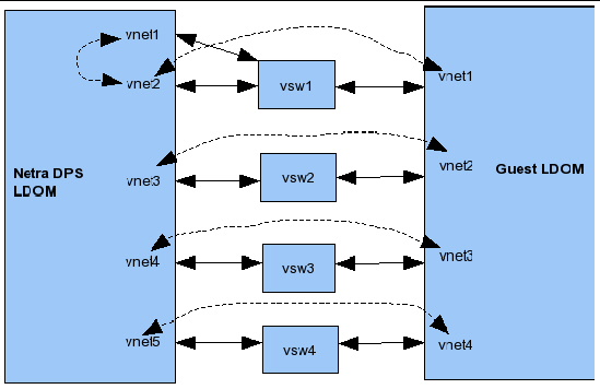
In this example, the dotted lines illustrate the direct connection between vnetinterfaces that are connected to the same vswitch.
The vnetinterfaces must be assigned IP addresses. Also, the ARP must be disabled on the vnetdevices used for the test. The IP addresses for the Sun Netra DPS vnetinterfaces are assigned during the test setup.
When testing with VLANs, the vnettest application expects the VLAN ID to start from 11 and continue upwards. For example, in the illustration above, the following are VLAN IDs that must be assigned to the interfaces:
The source code for the vnet reference application is in the SUNWndps package in the /opt/SUWNndps/src/apps/vnet_sample directory. The source code includes the following:
This section includes descriptions of how to build the vnet reference application.
build cmt1 | cmt2 10g | 10g_niu | 4g [2port][profiler][vlan]
The build script supports the following arguments:
Execute the following build command:
This command builds the Sun Netra DPS vnet application for the UltraSPARC T2 platform with VLAN tagging enabled for the test frames.
|
The Sun Netra DPS application is booted from a virtual network interface assigned to its domain.
|
1. Change directories to: /opt/SUNWndps/src/apps/vnet_sample/src/solaris
|
1. Change directories to: /opt/SUNWndps/src/apps/vnet_sample/src
2. Create a TAR file of the common and linux directories:
3. Copy the TAR file onto a system that has a cross-compiler for UltraSPARC T2.
4. Untar the file into a directory.
% mkdir testvnet-lnx % cp testvnet-srcs.tar testvnet-lnx % cd testvnet-lnx % tar -xvf testvnet-srcs.tar |
5. Change directories to the linux directory, and execute the make command.
|
1. Copy the testvnet binary into the guest logical domain.
2. Create a permanent, static ARP entry for the control vnet:
3. Start the testvnet application:
The application prompts you to enter the IP addresses for the Sun Netra DPS vnet interfaces and the guest logical domain vnet interfaces to be used in the test
4. Enter IP address for the local interface to be used:
After you enter all of the IP addresses, the test starts. The testvnet application prints statistical information to the console. The Sun Netra DPS application also prints statistical information on its console. The statistics correspond to the measurements made by each end.
The statistics on the guest logical domain are on a LWP basis. An example is shown below. If more than one interface is used and if n-threads are specified as the thread count, then threads 0 to n -1 are used for interface 0, threads n to (2 *n - 1) are used for interface 1, and so on.
The statistics on the Sun Netra DPS console are on a per-port basis. An example is shown below:
|
1. Copy the testvnet binary onto the guest logical domain.
2. Create a permanent, static ARP entry for the control vnet:
3. Start the testvnet application:
The application prompts you to enter the IP addresses for the Sun Netra DPS vnet interfaces and also the guest logical domain vnet interfaces to be used in the test.
After you have entered all of the IP addresses, the test starts. The testvnet application prints statistical information to the console. The Sun Netra DPS application also prints statistical information to its console. The statistics correspond to the measurements made by each end.
The statistics printed on the guest logical domain are on a LWP basis. An example is shown below. If more than one interface is used and if n-threads are specified as the thread count, then threads 0 to n -1 are used for interface 0, threads n to (2 *n - 1) are used for interface 1, and so on.
The statistics on the Sun Netra DPS console are on a per-port basis. An example is shown below:
| Netra Data Plane Software Suite 2.1 Update 1 User’s Guide | E20948-01 |
Copyright © 2011, Oracle and/or its affiliates. All rights reserved.
 To Compile the ipfwd Application