Troubleshooting and Operational Procedures
|
This appendix contains the following section:
Troubleshooting and Servicing the Array
The Sun StorageTek Common Array Manager Service Advisor provides array troubleshooting information and removal and replacement procedures for customer-replaceable units (CRUs). Service Advisor also includes field-replaceable units (FRUs) that can be replaced by Sun field engineers or by Sun-trained customer administrators.
To access Service Advisor:
1. Log in to Sun StorageTek Common Array Manager (CAM).
2. From the Storage System Summary page, click the name of the array you want to service.
3. At the top right of the page, click Service Advisor.
The Service Advisor opens in a new window.
4. Expand the Removal/Replacement procedure for the component you want to replace, and select the failed component.
The corresponding procedure is displayed in the right pane.
Service Advisor guides you through the following procedures:
- CRU and FRU Removal and Replacement
- Troubleshooting and Recovery
- X-Option upgrades
- Portable Virtual Disk Management
Controller Tray Components
FIGURE C-1 describes the components of the controller tray with the front bezel removed.
FIGURE C-1 Sun Storage 6580 and 6780 Array Controller Tray (Front View)
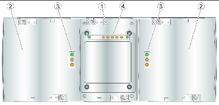
Figure Legend
|
1
|
Interconnect battery canister
|
3
|
Power supply-fan LEDs
|
|
2
|
Power supply-fan assemblies
|
4
|
Interconnect battery LEDs
|
TABLE C-1 Controller Tray Front LED Descriptions
|
LED
|
Symbol
|
Location
|
Function
|
|
Power
|

|
Power-fan
Interconnect battery
|
- On: The canister has power.
- Off: The canister does not have power.
Note: The controller canisters do not have a power LED. They receive their power from the power supplies inside the power-fan canisters.
|
|
Battery Needs Attention
|

|
Interconnect battery
|
On: A problem exists with the battery.
|
|
Service Action Allowed
|

|
Power-fan
Interconnect battery
|
On: You can remove the canister safely.
See Service Action Allowed LED.
|
|
Service Action Required
(Fault)
|

|
Power-fan
Interconnect battery
|
On: A problem exits with the canister.
|
|
Locate
|

|
Interconnect battery
|
On: A tray is located.
|
Service Action Allowed LED
Each controller canister, power-fan canister, and interconnect-battery canister has a Service Action Allowed LED, which is a blue LED. The Service Action Allowed LED lets you know when you can remove a canister safely.

|
Caution - Possible loss of data access. Never remove a controller canister, a power-fan canister, or an interconnect-battery canister unless the Service Action Allowed LED is turned on.
|
If a controller canister or a power-fan canister fails and must be replaced, the Service Action Required (Fault) LED (an amber LED) on that canister comes on to indicate that service action is required. The Service Action Allowed LED also comes on if it is safe to remove the canister. If data availability dependencies exist or other conditions that dictate a canister should not be removed, the Service Action Allowed LED stays off.
The Service Action Allowed LED automatically comes on or goes off as conditions change. In most cases, the Service Action Allowed LED comes on when the Service Action Required (Fault) LED comes on for a canister.
| Note - If the Service Action Required (Fault) LED comes on but the Service Action Allowed LED is off for a particular canister, you might need to service another canister first. Check your storage management software to determine the action that you should take.
|
Controller Tray Diagnostic Codes
TABLE C-2 Diagnostic Codes
|
Code
|
Description
|
L0
|
The controller types are mismatched.
|
L1
|
The interconnect-battery CRU is missing.
|
L2
|
A persistent memory error has occurred.
|
L3
|
A persistent hardware error has occurred.
|
L4
|
A persistent data protection error has occurred.
|
L5
|
The auto-code synchronization (ACS) has failed.
|
L6
|
An unsupported host interface card is installed.
|
L7
|
The sub-model identifier is not set or is mismatched.
|
L8
|
A memory configuration error has occurred.
|
Figure showing cable connections from controller tray to sixteen expansion trays.
About the Controller Tray ID Numeric Display and Diagnostic Display
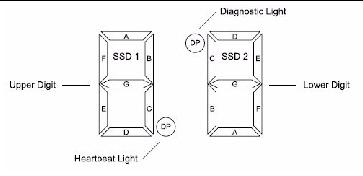
The Sun Storage 6580 and 6780 controllers have a pair of 7-segment displays located at the back of the controller tray that form a 2-digit display. This section defines the indicators and what conditions they represent when activated.
TABLE C-3 FC 4Gb Host Card LED Link Rate Indicators
|
L1
|
L2
|
Definition
|
|
Off
|
Off
|
No connection or link down
|
|
On
|
Off
|
1 Gb link rate
|
|
Off
|
On
|
2 Gb link rate
|
|
On
|
On
|
4 Gb link rate
|
Each digit has a decimal point, and is rotated 180 degrees relative to the other digit as shown in FIGURE C-2. With this orientation, the display looks the same regardless of controller orientation.
The decimal point for the lower digit is defined as the Diagnostic Light. The decimal point for the upper digit is defined as the Heartbeat light.
FIGURE C-2 Tray ID Display
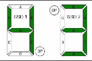
The values on each display (Controller A and Controller B) are shown as if the digits had the same orientation. For example, if the tray ID is set to 43, the top controller display might appear as shown in FIGURE C-3, while the bottom controller display would then appear as shown in FIGURE C-4.
FIGURE C-3 Controller A Tray ID Example
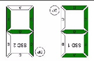
FIGURE C-4 Controller B Tray ID Example
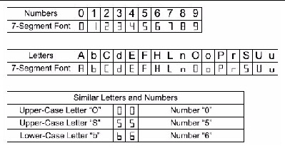
Alphanumeric characters are represented on the display as shown in FIGURE C-5. During normal operation, the tray ID display on each controller is used to display the enclosure tray ID. The display is also used for diagnostic codes. The Diagnostic Light indicates current usage. The Diagnostic Light is off when the display is used to show the current tray ID.
FIGURE C-5 Seven-Segment Alphanumeric Characters
The tray ID is an attribute of the enclosure. In other words, both controllers will always display the same tray ID. It is possible, however, that one controller may display the tray ID, while the other controller displays a diagnostic code.
Sequence Category Codes
TABLE C-4 defines the sequence category codes and their associated detail codes. Startup errors and operational states can be displayed in sequences by themselves. If the display is used to identify a component failure, information about the controller state in which the error was identified will also be displayed, as indicated in TABLE C-5.
| Note - If the Sun Storage 6580 or 6780 controller module is powered on when the interconnect canister is missing, or if Controller B is inserted when the interconnect canister is missing, the values shown on the Controller B tray ID display will be inverted.
|
TABLE C-4 Seven-Segment Display Sequence Code Definitions
|
|
Category Code
|
Detail Codes
|
|
Category
|
(Notation described in the notes at the end of this table)
|
|
Startup Error
|
SE+
|
- 88+ Power-on default
- dF+ Power-on diagnostic fault
|
|
Operational Error
|
OE+
|
- Lx+ Lock-down codes (Note 3)
|
|
Operational State
|
OS+
|
- OL+ Offline (held in reset, Note 11)
- bb+ Battery Backup (operating on batteries)
- CF+ Component failure (Note 12)
|
|
Component Failure
|
CF+
|
- dx+ Processor/Cache DIMM (x = location, Note 6)
- Cx+ Cache DIMM (x = location, Note 7)
- Px+ Processor DIMM (x = location, Note 8)
- Hx+ Host card (x = location)
- Fx+ Flash drive (x = location)
|
|
Category Delimiter
|
dash+
|
- Separator between category-detail code pairs (Notes 4, 9)
|
|
End-of-Sequence Delimiter
|
blank-
|
- End-of-sequence indicator (Notes 5, 10)
|
|
Note -
- xy+ 2-digit code with the Diagnostic light ON.
- xy- 2-digit code with the Diagnostic light OFF.
- Lx+ Lock-down codes (see Seven-Segment Display Lock-Down Codes).
- dash+ All segments off except for the middle segments and with the Diagnostic light ON.
- blank- All segments off with the Diagnostic light OFF.
- dx+ Used when there is a single memory system for processor and data cache.
- Cx+ Used when there are separate processor and data cache memory systems.
- Px+ Used when there are separate processor and data cache memory systems.
- Category-Detail separator used when there is more than one category-detail code pair in the sequence. See Table 38 for examples.
- End-of-Sequence indicator automatically inserted by hardware at the end of the sequence. Example: SE+ 88+ blank- (repeat)
- If a tray ID is being displayed, this sequence is programmed to display if the controller is subsequently held in reset.
- The tray ID is nominally displayed during normal operation. This operational state is displayed if an internal controller component failure occurs while the controller is online. An additional detail code identifies the failed component as defined for the Component Failure category. This sequence will continue to be displayed even if the controller is subsequently placed offline (held in reset) to service the failed component.
|
TABLE C-5 Seven-Segment Display Sequence Use Cases
|
Use Case
|
Repeating Sequence
|
|
Controller power-on
|
|
Normal power-on or controller insertion
|
SE+ 88+ blank-
|
|
Controller inserted while held in reset
|
SE+ 88+ blank-
|
|
Operational states
|
|
Normal operation
|
xy- (static controller tray ID)
|
|
Controller placed in reset while displaying tray ID
|
OS+ OL+ blank-
|
|
Controller is operating on batteries (cache backup)
|
OS+ bb+ blank-
|
|
Component failure when the controller is operational (Notes 1, 2)
|
|
Failed host card
|
OS+ CF+ Hx+ blank-
|
|
Failed flash drive
|
OS+ CF+ Fx+ blank-
|
|
Power-on diagnostic failure (Note 1)
|
|
Non-FRU component failure
|
SE+ dF+ blank-
|
|
Processor DIMM failure
|
SE+ dF+ dash+ CF+ Px+ blank-
|
|
Cache memory DIMM failure
|
SE+ dF+ dash+ CF+ Cx+ blank-
|
|
Processor/cache DIMM failure
|
SE+ dF+ dash+ CF+ dx+ blank-
|
|
Controller is suspended and there are no other errors to report
|
|
All lock-down conditions
|
OE+ Lx+ blank-
|
|
Controller is suspended due to component errors
|
|
Persistent processor DIMM ECC errors
|
OE+ L2+ dash+ CF+ Px+ blank-
|
|
Persistent cache DIMM ECC errors
|
OE+ L2+ dash+ CF+ Cx+ blank-
|
|
Persistent processor/cache DIMM ECC errors
|
OE+ L2+ dash+ CF+ dx+ blank-
|
|
Controller is suspended due to persistent cache backup configuration errors
|
|
Write-protect switch set during cache restore
|
OE+ LC+ blank-
|
|
Memory size changed with dirty data in flash drives
|
OE+ LC+ dd+ blank-
|
|
Note -
- If more than one component failure occurs, only the first component failure detected will be identified on the seven-segment display.
- If a component failure is indicated on the seven-segment display while the controller is operational, other event notification (MEL events, recovery guru procedures, etc.) that normally occurs for that condition will continue to occur.
|
Seven-Segment Display Lock-Down Codes
Diagnostic codes are used to indicate controller state information. In general, these codes are displayed only when the controller is in a non-operational state. The controller might be non-operational due to a configuration problem (such as mismatched controller types), or it might be non-operational due to a hardware fault. If the controller is non-operational due to system configuration, the controller Fault Light will be off. If the controller is non-operational due to a hardware fault, the controller Fault Light will be on.
TABLE C-6 provides a definition of the diagnostic lock-down codes. The code is displayed as a sequence.
TABLE C-6 Tray ID Display Diagnostic Codes
|
Value
|
Controller State
|
Description
|
|
L0
|
Suspended
|
Mismatched controller types
|
|
L1
|
Suspended
|
Missing interconnect canister
|
|
L2
|
Suspended
|
Persistent memory errors
|
|
L3
|
Suspended
|
Persistent hardware errors
|
|
L4
|
Suspended
|
Persistent data protection errors
|
|
L5
|
Suspended
|
ACS failure
|
|
L6
|
Suspended
|
Unsupported host card
|
|
L7
|
Suspended
|
Submodel identifier not set or mismatched
|
|
L8
|
Suspended
|
Memory configuration error
|
|
L9
|
Suspended
|
Link speed mismatch
|
|
LA
|
Suspended
|
Reserved
|
|
Lb
|
Suspended
|
Host card configuration error
|
|
LC
|
Suspended
|
Persistent cache backup configuration error
|
|
Ld
|
Suspended
|
Mixed cache memory DIMMs
|
|
LE
|
Suspended
|
Uncertified cache memory DIMM sizes
|
|
LF
|
Suspended
|
Lock-down with limited SYMbol support
|
|
LH
|
Suspended
|
Controller firmware mismatch
|
Expansion Tray LED Status Codes
The following is a list of the meanings of the status codes that may display on the numerical LEDs on the 6140 expansion trays.
FF - ESM Boot Diagnostic executing
88 - This ESM is being held in Reset by the other ESM
AA - ESM-A application is booting up
bb - ESM-B application is booting up
L0 - Mismatched ESM types
L2 - Persistent memory errors
L3 - Persistent hardware errors
L9 - Over Temperature
H1 - SFP Speed Mismatch (2 Gb/s SFP installed when operating at 4 Gb/s)
H2 - Invalid/Incomplete Configuration
H3 - Maximum Reboot Attempts Exceeded
H4 - Cannot Communicate with Other ESM
H5 - Midplane Harness Failure
H6 - Firmware Failure
H7 - Current Enclosure Fibre Channel Rate Different than Rate Switch
H8 - SFP(s) Present in Currently Unsupported Slot (2A or 2B)
Powering Off the Array
The array rarely needs to be powered off. You remove power only when you plan to physically move the array to another location.
To power off the array, do the following:
1. Stop all I/O from the hosts, if connected, to the array.
2. Wait approximately 2 minutes until all disk drive LEDs have stopped flashing.
After a 2-minute period, data residing in cache is written to disk and the battery mechanisms are disengaged.
| Note - If Media Scan is enabled (default), the disk drive LEDs will continue to flash after the 2-minute period has elapsed. However, the LED flash rate during a media scan (slow, periodic blink) is different from the flash rate of I/O (fast, random).
|
3. Check the Cache Active LED on the controller to determine if any outstanding cache needs to be written.
If the LED is on, there is still data that needs to be flushed and written to disk.
| Note - Ensure that the Cache Active LED is no longer flashing before powering off the array.
|
4. Press each power switch at the back of the controller tray to the Off position.
5. Press the power switches at the back of each expansion tray to the Off position.
| Hardware Installation Guide for Sun Storage 6580 and 6780 Arrays
|
820-5773-11
|
   
|
Copyright © 2009 Sun Microsystems, Inc. All rights reserved.


