|
Removing and Replacing a Power Supply |
This document describes how to replace the power supply in the Sun Disk Shelf-24x3.5” SAS-2 and in the Sun Storage J4400 Array.

|
Caution - Only trained service personnel should remove the covers on this equipment. |
This product is intended for restricted access, whereby access is controlled through the use of a means of security (for example, key, lock, tool, badge access), and personnel authorized for access have been instructed on the reasons for the restrictions and any precautions that they need to take.
This document assumes that you have:
When performing this service action, observe the following electrostatic discharge (ESD) precautions:
Each chassis contains two hot-swappable, redundant power supplies. If one power supply is turned off or malfunctions, the other power supply maintains electrical power. Each power supply contains two internal fans that provide cooling for the system.
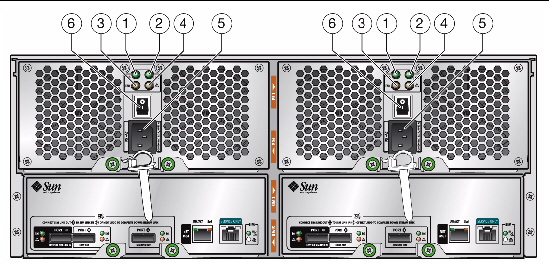
FIGURE 1 identifies the power supply components.
| Note - FIGURE 1 shows the Sun Disk Shelf-24x3.5” SAS-2. On the Sun Storage J4400 Array, the connectors and LEDs on the SIM boards at the bottom of the system are arranged differently. However, the power supply connectors and LEDs identified in FIGURE 1 are the same for both systems. |
FIGURE 1 Power Supply LEDs and Components (Back View)

To replace a failed power supply, you must complete the following steps, which are described in detail in the remainder of this guide:
1. Remove the failed power supply. See To Remove a Failed Power Supply.
2. Install the replacement power supply. See To Install a New Power Supply.
3. Verify the installation. See To Verify the Installation.

|
Caution - Potential loss of data access. Never remove a power supply unless the power fault LED or fan fault LED is amber (FIGURE 1). |
|
1. From the back of the cabinet, locate the failed power supply.
The power supply fault or fan fault LED is amber (FIGURE 1).
2. Ensure that the power supply on/off switch is in the “O” (off) position.
3. Remove the power cord tie strap from the power cord.
4. Unplug the power cord from its power supply connector.
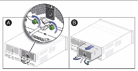
5. Remove the power supply from the system (FIGURE 2):
a. Loosen the two captive screws on the power supply ejection levers.
| Note - You might need a Phillips No. 2 screwdriver to loosen the screws. |
b. Swing the ejection levers fully outward to eject the power supply from the chassis.

|
Caution - Be careful to not damage the circuit board connector extending from the back of the power supply. |
FIGURE 2 Removing a Power Supply

|

|
Caution - Follow all ESD precautions (see ESD Precautions) and use care when handling either the new or failed power supply. |
1. Unpack the new power supply.

|
Caution - Be careful to not damage the circuit board connector extending from the back of the power supply. |
2. Place the failed power supply in the packing materials so that you can return it to Oracle for proper disposal.
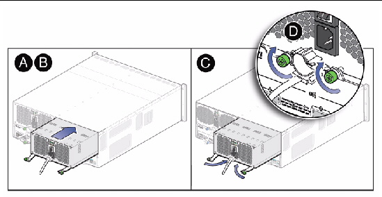
3. Insert the new power supply into the chassis by completing the following steps (FIGURE 3):
a. Swing both ejection levers to the fully open position.
b. Align the power supply with the open slot and slide it into the chassis until it engages with the chassis connectors and the ejection levers begin to swing closed.
c. Simultaneously push both ejection levers toward the middle of the power supply to seat it in the chassis.
d. Tighten the two ejection lever captive screws to secure the power supplies.
FIGURE 3 Installing a Power Supply

4. Ensure that the power supply on/off switch is in the “O” (off) position.
5. Plug the power cord into the new power supply and attach the power cord tie strap to the power cord.
|
1. Place the power supply on/off switch to the “I” (on) position.
2. Verify that the AC and DC power LEDs are lit steady green and that the power supply fault LED is off.
We are interested in improving the product documentation and welcome your comments and suggestions. Submit comments about this document by clicking the Feedback[+] link at:
Please include the title and part number of your document with your feedback:
Sun Disk Shelf-24x3.5" SAS-2 and Sun Storage J4400 Array Power Supply Replacement Guide, part number 820-7245-11
Copyright © 2010, Oracle and/or its affiliates. All rights reserved.