| C H A P T E R 1 |
|
Installing, Connecting, and Testing the Host Adapter |
This chapter describes the Sun StorageTek PCI-E Dual Channel Ultra320 SCSI HBA (host bus adapter) and explains how to install it into a host, connect it to SCSI storage devices, test the installation, and boot from a disk drive connected to the host adapter.
|
Note - If you are unfamiliar with Ultra320 SCSI configuration guidelines, read Ultra320 SCSI Configuration before performing the procedures in this chapter. |
This chapter contains the following sections:
The Sun StorageTek PCI-E Dual Channel Ultra320 SCSI host bus adapter (HBA) is a low-profile single-slot, expansion board that interfaces a PCI Express (PCIe) x4 bus to two independent Ultra320 SCSI channels. The PCI Express interface has four full-duplex PCIe lanes and supports the PCIe r1.0a specification.

The host adapter includes the following features:
You can use the Sun StorageTek PCI-E Dual Channel Ultra320 SCSI HBA with the following operating systems (OSs):
Before you start, read these instructions, as well as the installation instructions for the storage devices to be connected to the host adapter. Also, before installing the host adapter, read Release Notes for required information, including lists of supported host systems, cables, and storage devices.

|
Caution - This host adapter is only for connection to a single-ended (SE) or low-voltage differential (LVD) device, and it does not work if connected to a high-voltage differential (HVD) device. See SCSI Symbolsfor images of the SCSI symbols. |
|
1. Read and observe the safety information at the back of this book.
See Safety Agency Compliance Statements.
2. Install Solaris 10 HW2 (minimum version for SPARC) or Solaris 10 x86 HW1 (minimum version for x86/x64) on the target host system.
3. Download and install the latest Solaris 10 (either SPARC or x86) recommended patch cluster on the host, as described in Release Notes.
4. Install any required driver patches on the host, as described in Release Notes.

|
Caution - If the driver and any required patches described in the release notes are not installed, you might not be able to use the host adapter. |
5. Install the SunVTS software on the host.
The SunVTS software is shipped on the Supplemental Software CD-ROM along with the Solaris OS CD-ROM. Read the user's guide listed in Before You Read This Book for instructions on installing the SunVTS software.
6. Exit the operating environment.
To inform any mounted users that the system will be going down, use the shutdown command. Otherwise, use the init 0 command. See the man pages for these commands or the Solaris AnswerBook documentation.
For instructions, refer to the service documentation that came with your system.
You are now ready to unpack and install the host adapter as described in the following text.
1. Unpack the box containing the host adapter.
|
Note - Leave the host adapter in the protective bag until you are ready to install it. |

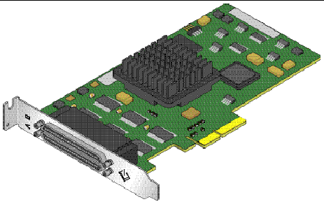
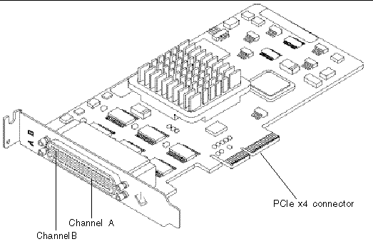
The host adapter is shown in Figure 1-2. The Very High Density Cable Interconnect (VHDCI) connectors are for the VHDCI cables that are used to connect the host adapter to the storage device.
2. Power off the computer, then disconnect the power cable.
Refer to your system documentation for information about how to open the system.
4. Remove the filler panel for the desired slot.
Refer to the system documentation for information about removing filler panels.
5. Remove the host adapter from its protective bag.
6. Select an empty PCI Express slot that can support a PCIe x4 card for this host bus adapter, and install the host bus adapter in that slot.
Refer to the system's hardware documentation for information about mounting details (mounting holes, standoff locking/unlocking, and screws to secure the card).

|
Caution - Using excessive force can bend or damage the host adapter edge connector. Make sure that the edge connector is properly aligned before pressing the adapter into place. The bracket around the two external connectors should fit into the empty space where the filler panel was removed in Step 4. |
7. If necessary, replace the low profile PCI bracket with a standard height PCI bracket in order to fit into a standard height PCI-E slot.
The next two sections describe how to connect the host adapter to one or more storage devices and how to test the host adapter.
Before you connect the host adapter to the storage devices, do the following:
|
 Connect the host adapter to the storage devices using the appropriate cables.
To test the host adapter installation in a Solaris environment, use SPARC OBP probe-scsi-all command, Solaris (SPARC or x64/x86) format command, or SunVTS disktest if the attached storage target is a disk array
|
1. If you have disconnected the power cable, reconnect it.
2. Power on the connected storage device, and then power on the host.
3. Bring the system down to the ok prompt at run level 0.
|
Note - If the host starts to reboot, interrupt the reboot process by pressing the Stop and A keys simultaneously. |
4. At the ok prompt, issue the probe-scsi-all command to verify that the system recognizes the host adapter.
The probe-scsi-all command displays the SCSI devices connected to the host, as shown in the following screen example.
ok probe-scsi-all /pci@4,2000/pci@1/scsi@2 Target 0 Unit 0 DISK SEAGATE ST336605LSUN36G 0238 /pci@4,2000/pci@1/scsi@2,1 Target 0 Unit 0 DISK SEAGATE ST336605LSUN36G 0238 |
In this example, the first SCSI port (scsi@2) has one disk drive connected
(Target 0). The second SCSI port (scsi@2,1) also has one disk drive connected (Target 0). In the illustration of the host adapter in FIGURE 1-2, the first SCSI port is labeled as Channel A; the second SCSI port as Channel B.
|
Use the following procedure to test the host adapter installation using the format command on a Solaris 10 for x64/x86 platform.
1. Become a root user and type the format command.
2. When prompted, type the number of the disk drive that is attached to the host adapter card you just installed and press Enter.
3. Type analyze to select the type of test.
4. Type read to further define the type of test, and then yes to continue.
5. Verify that no error occurred, as indicated by the output line Total of 0 defective blocks repaired. Contact your service provider if an error was observed.
6. Issue two quit commands to exit the test and the Format menu.
Your Sun StorageTek PCI-E Dual Channel Ultra320 SCSI HBA is ready for use.
|
Use the SunVTS software to test a disk on a newly attached disk array in order to verify that the host adapter is properly installed.
For details about running the SunVTS software, refer to the SunVTS 6.X User's Guide and the SunVTS 6.X Test Reference Manual.
|
Note - Refer to the SunVTS documentation to determine whether the host platform is supported. |
1. As superuser, open the SunVTS window.
2. From the System Map, select a disk drive that is in an array connected to the host adapter.
4. Verify that no errors have occurred by checking the SunVTS status window.
5. If no problems occur, stop the SunVTS software.
Your host adapter is now ready to run applications.
|
Note - If problems occur, please contact your service provider for assistance. |
The Sun StorageTek PCI-E Dual Channel Ultra320 SCSI HBA uses the Solaris mpt device driver, which is included in the Solaris 10 (SPARC or x64/x86) OS. This enables you to install Solaris 10 to a hard disk connected to the host adapter and 'warm' boot directly from the disk.
After booting, install any required patches for the mpt driver. Refer to Release Notes for instructions on downloading and installing mpt driver patches.
|
Note - The Sun StorEdge 3310 standalone SCSI array is presently limited to Ultra160 SCSI bus speeds only. Normally, the host adapter automatically lowers the transfer speed for attached storage devices that are not Ultra320 capable. However, for the Sun StorEdge 3310 standalone SCSI array, you must create an mpt.conf file to limit the Sun StorageTek PCI-E Dual Channel Ultra320 SCSI HBA to Ultra160 SCSI bus speeds. For instructions on creating the mpt.conf file, refer to the Release Notes. |
|
During system booting, the BIOS initialization screen is displayed.
2. Immediately press Control-C.
The LSI Logic MPT SCSI Setup Utility menu is displayed.
In this example there are three Sun StorageTek PCI-E Dual Channel Ultra320 SCSI HBAs installed in PCI slots J1, J2, and J3, and the one in PCI slot J3 uses Channel B (indicated by Dev/Func = 51) to connect to the storage device that contains the external boot disk.
3. Press F2 as required to highlight <Boot Adapter List> in the second line of the menu, then press Enter.
The following information is displayed:
4. Use the arrow keys to highlight the HBAs in the Next Boot column and use the -/+ keys to disable all except the selected HBA that has external boot disk attached.
The following information is displayed:
Boot property changes have been made <Cancel Exit> Exit the Configuration Utility <Save Changes then exit this menu> <Discard changes then exit this menu> |
6. Use the arrow key to highlight <Save Changes then exit this menu> and press Enter.
The LSI Logic MPT SCSI Setup Utility menu is displayed.
7. To prevent any disk drives attached to Sun StorageTek PCI-E Dual Channel Ultra320 SCSI HBA from being used as the boot disk, use the arrow key to highlight the HBA that has the external boot disk attached, then press Enter.
The following information is displayed:
8. Ensure that <Device Properties> is highlighted, then and press Enter.
The following information is displayed:
9. Use the arrow key to highlight the disk drives in the Scan ID column and use the -/+ key to change them from Yes to No. Do not change the boot disk.
|
Note - In the example above, SCSI ID 7 indicates the HBA with the external boot disk attached, and SCSI ID 8 indicates the external boot disk. |
10. Press the Escape key twice.
The following information is displayed:
Adapter and/or device property changes have been made <Cancel Exit> Exit the Configuration Utility <Save Changes then exit this menu> <Discard changes then exit this menu> |
11. Use the arrow key to highlight <Save Changes then exit this menu> and press Enter.
13. Use the arrow key to highlight Exit the Configuration Utility and press Enter.
14. Press any key to reboot the system.
Copyright © 2006, Sun Microsystems, Inc. All Rights Reserved.