| Sun Fire X2270 Server Service Manual |
| A P P E N D I X C |
|
Installing the Server Into a Rack With Optional Slide Rails |
Perform the procedures in this chapter to install your server into a four-post rack using the orderable slide rail option. These slide rails are compatible with a wide range of equipment racks that meet the following standards:
Use this procedure to remove the mounting brackets from the slide rail assemblies.
2. Locate the slide rail lock at the front of one of the slide rail assemblies, as shown in FIGURE C-1.
3. Squeeze and hold the tabs at the top and bottom of the lock while you pull the mounting bracket out of the slide rail assembly until it reaches the stop.
See FIGURE C-1.
4. Push the mounting bracket release button toward the front of the mounting bracket, as shown in FIGURE C-1, and simultaneously withdraw the mounting bracket from the slide rail assembly.
5. Repeat for the remaining slide rail assembly.
FIGURE C-1 Disassembling the Slide Rail Before Installation

Use this procedure to install the mounting brackets onto the sides of the server.
1. Position a mounting bracket against the chassis so that the slide rail lock is at the server front, and the four keyed openings on the mounting bracket are aligned with the four locating pins on the side of the chassis.
FIGURE C-2 Aligning the Mounting Bracket With the Server Chassis

2. With the heads of the four chassis locating pins protruding though the four keyed openings in the mounting bracket, push the mounting bracket toward the front of the chassis until the mounting-bracket clip locks into place with an audible click.
See FIGURE C-2.
3. Verify that the rear locating pin has engaged the mounting-bracket clip.
See FIGURE C-2.
4. Repeat Steps 1 through 3 to install the remaining mounting bracket on the other side of the server.
Use this procedure to install the slide rail assemblies to the rack.
1. Position a slide rail assembly in your rack so that the brackets at each end of the slide rail assembly are on the outside of the front and rear rack posts.
See FIGURE C-3.
2. Attach the slide rail assembly to the rack posts, but do not tighten the screws completely.
The method used to attach the slide rails varies, depending on the type of rack:
FIGURE C-3 Slide Rail Assembly Mounting to Rack Post

3. Repeat Step 1 and Step 2 for the remaining slide rail assembly.
4. From the front of the rack, set the proper width of the rails with the spacer.
See FIGURE C-4.
FIGURE C-4 Setting the Rail Width
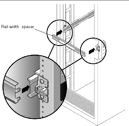
5. Tighten the screws on the brackets.
6. Remove the spacer and confirm that the rails are attached tightly to the rack.
7. Repeat Step 4 through Step 6 for rear of the rack.
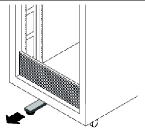
8. If available, extend the anti-tilt bar at the bottom of the rack.
See FIGURE C-5.
FIGURE C-5 Extending the Anti-tilt Bar

|
Caution - If your rack does not have an anti-tilt bar, there is some danger of the rack tipping. |
Use this procedure to install the server chassis, with mounting brackets, into the slide rail assemblies that are mounted to the rack.
|
|
Caution - This procedure requires a minimum of two people because of the weight of the server. Attempting this procedure alone could result in equipment damage or personal injury. |
1. Push the slide rails into the slide rail assemblies in the rack as far as possible.
2. Raise the server so that the rear ends of the mounting brackets are aligned with the slide rail assemblies that are mounted in the equipment rack.
See FIGURE C-6.
3. Insert the mounting brackets into the slide rails, then push the server into the rack until the mounting brackets encounter the slide rail stops (approximately 12 inches, or 30 cm).
FIGURE C-6 Inserting the Server With Mounting Brackets Into the Slide Rails

4. Simultaneously push and hold the slide rail release buttons on each mounting bracket while you push the server into the rack. (See FIGURE C-6.) Continue pushing until the slide rail locks on the front of the mounting brackets engage the slide rail assemblies.
You will hear an audible click.
|
|
Caution - Verify that the server is securely mounted in the rack and that the slide rails locks are engaged with the mounting brackets before continuing. |
Use this procedure to ensure that the slide rails are operating correctly.
| Note - Two people are recommended for this procedure: one to move the server in and out of the rack, and one to observe the cables. |
1. Slowly pull the server out of the rack until the slide rails reach their stops.
2. Inspect the attached cables for any binding or kinks.
3. Push the server back into the rack, as described below.
When the server is fully extended, you must release two sets of slide rail stops to return the server to the rack:
a. The first set of stops are levers, located on the inside of each slide rail, just behind the back panel of the server. These levers are labeled “PUSH.” Push in both levers simultaneously and slide the server toward the rack.
The server will slide in approximately 38 cm (15 inches) and stop.
Verify that the cables retract without binding before continuing.
b. The second set of stops are the slide rail release buttons, located near the front of each mounting bracket. (See FIGURE C-6.) Simultaneously push or pull both of the slide rail release buttons and push the server completely into the rack until both slide rail locks engage.
4. Adjust the cable hangers as required.
| Sun Fire X2270 Server Service Manual | 820-5607-11 |
Copyright © 2009 Sun Microsystems, Inc. All rights reserved.