Chapter 21 Overview of PPP
This chapter presents an overview of Solaris Point-to-Point Protocol (PPP), a data-link protocol included in the TCP/IP protocol suite. The text includes product specifications, introductions to the most typical PPP configurations, and definitions of the terms related to PPP.
Overview of Solaris PPP
PPP enables you to connect computers and networks at separate physical locations by using modems and telephone lines. With PPP, users with computers at home or in remote offices can connect to your site's network. You can also use the combination of PPP software, a modem, and telephone lines as a router connecting networks in different places. PPP offers strategies for configuring these machines and networks, which are introduced in this chapter.
Solaris PPP Specifications
Solaris PPP is an asynchronous implementation of the standard data-link level PPP included in the TCP/IP protocol suite and provided by a number of router system vendors and terminal concentrators. It includes a standard encapsulation protocol, making datagram transmission transparent to network layer protocols.
The major characteristics of the Solaris PPP protocol are:
-
Implements the Internet Point-to-Point Protocol, as defined in RFC 1331
-
Provides error detection through CRC
-
Supports full-duplex transmission
The major functions of the protocol are:
-
Interface for IP to forward packets over asynchronous serial lines
-
Connection establishment on demand
-
Configurable options negotiation
-
Connection termination (automatic hang-up)
Transmission Facilities Used by PPP
PPP supports interfaces to RS-232-C (V.24) facilities through the CPU serial ports included on most machines running the Solaris software. In addition, PPP runs over optional asynchronous serial ports supplied or supported by many manufacturers of machines that run the Solaris software. PPP supports the maximum data rates that your machine's serial ports can achieve. Consult the manufacturer of your computer system for more details on the speeds supported by your machine's serial hardware.
Standards Conformance
PPP, and the routing functions in the Solaris software, use industry-standard conventions for performing their tasks. These conventions support:
-
Forwarding of IP datagrams
-
Reception of packets for forwarding from any IP-compatible networked system
-
Delivery of packets to any IP-compatible networked system on local-area network media, such as Ethernet, Token Ring, and FDDI
-
Use of standard routing protocols, enabling users to exchange packets with equipment that supports the PPP protocol from many manufacturers
PPP Network Interfaces
PPP enables asynchronous devices, such as modems, to become network interfaces. Solaris PPP enables you to configure two types of virtual network interfaces, ipdptpn and ipdn. (The letter n represents the device number you assign to the interface.)
PPP network interfaces are considered virtual network interfaces because they do not involve network hardware, as does, for example, an Ethernet interface. Moreover, they are not associated with any particular serial port. The PPP network interfaces reside in the /devices directories along with the physical network interfaces. (For information on physical network interfaces, see "Network Interfaces".)
The type of network interface you use depends on the PPP communications link you want to set up. The ipdptp interface supports point-to-point PPP links; the ipd interface supports point-to-multipoint links (called "multipoint links").
Extending Your Network With PPP
This section introduces PPP-related communications concepts. It also explains the most typical PPP configurations that you are likely to set up.
Point-to-Point Communications Links
The most common use of Solaris PPP is to set up a point-to-point communications link. A generic point-to-point communications configuration consists of two endpoints connected by a communications link. In a generic configuration, an endpoint system could be a computer or terminal, either in an isolated location or physically connected to a network. The term communications link refers to the hardware and software connecting these endpoint systems. The following figure illustrates these concepts.
Figure 21-1 Basic Point-to-Point Link

Dial-out Operations and Outbound Communications
When an endpoint system wants to communicate with the endpoint on the other side of the communications link, it begins a dial-out operation. For example, to communicate with endpoint B, a user at its peer host, endpoint A, types rlogin end-point-B. This causes endpoint A to dial out over the communications link. In this instance, endpoint A functions as a dial-out machine. The rlogin command causes its modem to dial the phone number of endpoint B. The action endpoint A starts and information it passes are considered outbound communications.
Dial-ins and Inbound Communications
When the data travels over the link to endpoint B, this system receives incoming data and sends an acknowledgment signal to endpoint A to establish communications. In this instance, endpoint B functions as a dial-in machine, since it permits other systems to dial in to it. The information passed to the communications recipient and the actions the recipient takes are considered inbound communications.
Point-to-Point Configurations Supported by Solaris PPP
Solaris PPP supports four types of point-to-point configurations:
-
Host in one location connected to a host at another physical location, as shown in Figure 21-1
-
Dial-in servers with dynamic point-to-point links to remote hosts, as shown in Figure 21-2
-
Network connected to another physically distant network, as shown in Figure 21-3
-
Computers connected to a multipoint dial-in server physically attached to a distant network, as shown in Figure 21-4
These PPP links provide essentially the same type of connectivity provided by a local area network but without broadcast capability. The following sections summarize the configuration types; Chapter 22, Planning for PPP gives information for setting up each configuration type.
Two Isolated Hosts Connected by a Point-to-Point Link
PPP enables you to set up a point-to-point link to connect two standalone machines in separate locations, effectively creating a network consisting solely of these two machines. This is the simplest point-to-point configuration because it involves only the two endpoints. The generic configuration shown in Figure 21-1 also uses the host-to-host configuration.
Nomadic Machines Connected to a Dial-in Server
In the past, standard dial-up or temporary connections permitted only ASCII terminals to connect to a network. With Solaris PPP, an individual machine can become part of a physically distant network by configuring it as one endpoint of the PPP link. The advantage of this nomadic connection is particularly apparent if your network includes users who travel frequently or work from home.
Figure 21-2 shows nomadic computers, each with a point-to-point link to an endpoint system on the network. The endpoint on the network is a dial-in server.
Figure 21-2 Nomadic Computers and Dynamic Link Dial-in Server
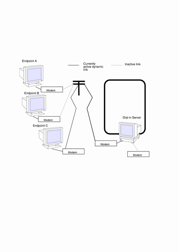
Dial-in Server With Dynamic Point-to-Point Link
The endpoint machine on the network shown in Figure 21-2 functions as a dial-in server with dynamic point-to-point links. It is called a dial-in server because remote machines can dial in to it to reach the network. When the server receives a request to dial in from a machine, the server allocates the PPP link to the machine on an as-needed basis.
A dial-in server can communicate with the remote hosts through a dynamic point-to-point link or through a multipoint link, as explained in "Multipoint Communications Links". The dynamic point-to-point link has the advantages of point-to-point communications: RIP can run over the link, and broadcasting is enabled. Perhaps most importantly, more than one machine on the physical network can function as the dial-in server. This allows you to configure backup servers, thus enabling redundancy and easier administration. Although the machines in Figure 21-2 can directly communicate with the network endpoint, they cannot directly communicate with each other. They must pass information to each other through the dial-in server endpoint.
Two Networks Connected by Point-to-Point Link
You can use PPP to connect two separate networks through a point-to-point link, with one system on each network serving as an endpoint. These endpoints communicate through modems and phone lines, essentially in the same fashion as shown in Figure 21-1. But in this setup, the endpoints, modems, and PPP software become routers for their physical networks. Using this type of configuration scheme, you can create an internetwork with wide geographic reach.
The following figure shows two networks in different locations connected by a point-to-point link.
Figure 21-3 Two Networks Connected by a PPP Link
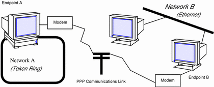
In this example, endpoints A and B, their modems, public telephone lines, and the PPP software act as a router between the networks. These networks might have other hosts serving as routers between physical networks. Sometimes, the host functioning as the PPP router might have an additional network interface board, thus also serving as a router for a physical network.
Multipoint Communications Links
You can use Solaris PPP to set up a multipoint communications link. In this type of configuration, an individual machine functions as one endpoint on the communications link. At the other end of the link might be several endpoint machines. This differs from point-to-point configurations, with a single endpoint system at either side of the communications link.
Figure 21-4 Nomadic Computers and Multipoint Dial-in Server
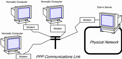
Multipoint Configurations Supported by PPP
Two types of multipoint links you can configure with PPP are:
-
Dial-in server with multipoint connections to remote machines, as shown in Figure 21-4
-
Logical, or virtual, network consisting of three or more nomadic computers, as shown in Figure 21-5
The following sections summarize these configurations; Chapter 22, Planning for PPP explains how to set up the configuration.
Multipoint Dial-in Servers
Figure 21-3 shows three geographically isolated computers communicating through a point-to-point link to an endpoint machine on a network. However, the network endpoint machine can communicate with the nomadic computers through a multipoint link, thus making it a multipoint dial-in server. (You can also set up a dial-in server with dynamic point-to-point connections, as explained in "Dial-in Server With Dynamic Point-to-Point Links".)
The dial-in server can communicate with all the machines on the other end of its multipoint PPP link. Though the machines in Figure 21-4 can directly communicate with the multipoint dial-in server, they cannot communicate directly with each other. They must pass information to each other through the dial-in server.
Virtual Networks
You can use PPP to set up a virtual network wherein the modems, PPP software, and telephone wires become the "virtual" network media. In a physical network, such as Ethernet or Token Ring, computers are directly cabled to the network media. In a virtual network, no true network media exist.
Machines become peer hosts on the virtual network when you configure each with a multipoint communications link. Then each host can dial out through its modem over phone lines to reach another endpoint machine. Each computer also functions as a dial-in machine, permitting its peer hosts on the virtual network to dial in to it.
The following figure depicts a virtual network consisting of nomadic computers connected to each other through modems and telephone lines.
Figure 21-5 Virtual Network of Nomadic Computers
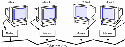
Each machine exists in a different office, perhaps in a different town from other members of the virtual network. However, each machine can establish communications with its peer hosts over its multipoint communications links.
Introducing the PPP Software
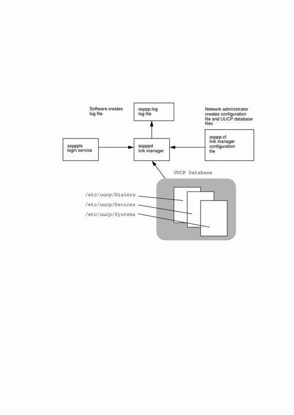
The PPP component software includes:
-
Link manager (/usr/sbin/aspppd)
-
Login service (/usr/sbin/aspppls)
-
Configuration file (/etc/asppp.cf)
-
Log file (/var/adm/log/asppp.log)
-
FIFO file (/tmp/.asppp.fifo)
After you install the PPP software, you will find the /etc/init.d/asppp file, which is the run-control script for PPP. It is linked to several other files in the run-control directories.
The following figure shows the software components of PPP and how they interact.
Figure 21-6 PPP Component Software
Link Manager
The /usr/sbin/aspppd link manager is a user-level daemon that automates the process of connecting to a remote host when PPP service is required. This automated process starts whenever any activity that generates IP traffic takes place (for example, a user logs in to a remote machine, accesses an NFS mounted file, and so on). If a remote host tries to establish a connection, the link manager on the local host will complete the connection.
Refer to the aspppd(1M) man page for specific information about the link manager.
Login Service
The /usr/sbin/aspppls login service is invoked as a login shell that starts PPP after you dial up and log in. Its function is similar to the /usr/lib/uucp/uucico command described in "UUCP Software". When configuring a machine as a dial-in server, you must specify aspppls as the login shell in the /etc/passwd file in the entries for every nomadic computer allowed to dial in to the local host.
Configuration File
The asppp.cf file provides the link manager with information about each remote endpoint with which the local host will communicate. You define this information in a section of the configuration file called a path. The path section also defines the PPP interface to be used and, optionally, other attributes determining how communications will take place, including security issues. "Parts of Basic Configuration File" explains the sections of the asppp.cf file in detail. The following example shows an unmodified asppp.cf file.
Example 21-1 Unmodified asppp.cf File
#ident	"@(#)asppp.cf	10	93/07/07 SMI"
#
# Copyright (c) 1993 by Sun Microsystems, Inc.
#
# Sample asynchronous PPP /etc/asppp.cf file
#
#

ifconfig ipdptp0 plumb mojave gobi private up

path
   inactivity_timeout 120    # Approx. 2 minutes
   interface ipdptp0
   peer_system_name Pgobi    # The name this system logs in with when
                             # it dials this server
                             # *OR* the entry we look up in
                             # /etc/uucp/Systems when we dial out.
|
Log File
The link manager produces messages and logs them in the log file /var/adm/log/asppp.log. The level of detail reported into the file is controlled by the -d option of aspppd or the debug_level keyword in the configuration file. See "Configuration Keywords" and the aspppd(1M) man page for more information.
FIFO File
The PPP FIFO file /tmp/.asppp.fifo is a named pipe used to communicate between aspppd and aspppls. This file must be present in /tmp for the PPP login service to connect to the link manager. The /tmp/.asppp.fifo file is created, managed, and deleted by the link manager.
UUCP Databases
Besides its component software, Solaris PPP uses information in three UUCP files, /etc/uucp/Systems, /etc/uucp/Dialers, and /etc/uucp/Devices, to help it establish the communications link. You must modify these files to enable a host to dial out over the PPP link. Alternatively, you can use the file /etc/uucp/Sysfiles to specify different names for the Systems, Devices, and Dialers files.
Refer to Chapter 25, Overview of UUCP for full descriptions of the UUCP files.
How the Components Work Together
This section describes how the components of PPP function for outbound and inbound connections.
Outbound Connections Scenario
Outbound communications begin when a user on one endpoint host initiates an activity involving the peer host on the other end of the PPP link. The following activities take place when a user types an rcp command to copy a file from a host on the other side of the link.
-
rcp sends the data through the levels of the TCP/IP protocol stack.
-
A virtual network interface (ipdn or ipdptpn) receives the data in the form of IP packets.
-
The interface sends the aspppd link manager a connection request that initiates an outbound connection.
-
The link manager then:
-
Verifies that the connection request corresponds to a configured path in the /etc/asppp.cf configuration file.
-
Consults the UUCP database files (/etc/uucp/Systems, /etc/uucp/Devices, and /etc/uucp/Dialers) for specific information about the modem and destination system.
-
Places a phone call to the destination host or attaches to the appropriate hardwired serial line.
-
-
The physical link to the peer host is established.
-
The link manager configures and initiates PPP.
-
The data-link layer is established, and the PPP modules on the peer host start communicating.
-
The link manager enables IP over the link.
The link manager then monitors the connection until an event, such as an idle timeout, line disconnect, or error condition, occurs. When any of these events occurs, the link manager disconnects from the peer host and returns to the idle state.
Inbound Connections Scenario
The host initiating the inbound communication logs in, which invokes the /usr/sbin/aspppls login service. Then the following events occur:
-
The login service connects to the link manager through the /tmp/.asppp.fifo file.
-
The login service provides the link manager with information such as the login name used by the endpoint at the other end of the link.
-
The link manager uses this login name to find a corresponding configured path in the configuration file.
-
The link manager then configures and initiates PPP.
-
The data-link layer is established, and the PPP modules on the peer hosts start communicating.
-
The link manager enables IP over the link.
The link manager then monitors the connection until an event occurs such as an idle time out, line disconnect, or error condition. When any of these events occur, the link manager disconnects from the peer and returns to the idle state.
PPP Security
After you have completed installing PPP on every machine involved in your configuration, you can add either one or two levels of security for the PPP link.
The first level, Password Authentication Protocol (PAP), is the least secure. A password is sent over the circuit "in the clear" until authentication is acknowledged or the connection terminated.
The second level of security, Challenge-Handshake Authentication Protocol (CHAP), periodically verifies the identity of the peer--the other end of the point-to-point link. A challenge message is sent to the peer by the authenticator--the system starting the link or challenge. The response is checked against a "secret" not sent over the link, and if the values match, authentication is acknowledged. Otherwise, the link is terminated. The process of adding PPP security is described in "Editing asppp.cf for PAP/CHAP Security".
- © 2010, Oracle Corporation and/or its affiliates
