Chapter 2 Metadevices
This chapter covers the different types of metadevices available in DiskSuite. Use the following table to proceed directly to the section that provides the information you need.
Simple Metadevices
A simple metadevice is a metadevice built only from slices, and is either used directly or as the basic building block for mirrors and trans metadevices. There are three kinds of simple metadevices: concatenated metadevices, striped metadevices, and concatenated striped metadevices.
In practice, people tend to think of two basic simple metadevices: concatenated metadevices and striped metadevices. (A concatenated stripe is simply a striped metadevice that has been "grown" from its original configuration by concatenating slices.)
Simple metadevices enable you to quickly and simply expand disk storage capacity. The drawback to a simple metadevice is that it does not provide any data redundancy. A mirror or RAID5 metadevice can provide data redundancy. (If a single slice fails on a simple metadevice, data is lost.)
You can use a simple metadevice containing multiple slices for any file system except the following:
-
Root (/)
-
/usr
-
swap
-
/var
-
/opt
-
Any file system accessed during an operating system upgrade or installation
Note -
When you mirror root (/), /usr, swap, /var, or /opt, you put the file system into a one-way concatenation (a concatenation of a single slice) that acts as a submirror. This is mirrored by another submirror, which is also a concatenation.
Concatenated Metadevice (Concatenation)
A concatenated metadevice, or concatenation, is a metadevice whose data is organized serially and adjacently across disk slices, forming one logical storage unit.
You would use a concatenated metadevice to get more storage capacity by logically combining the capacities of several slices. You can add more slices to the concatenated metadevice as the demand for storage grows.
A concatenated metadevice enables you to dynamically expand storage capacity and file system sizes online. With a concatenated metadevice you can add slices even if the other slices are currently active.
Note -
To increase the capacity of a striped metadevice, you would have to build a concatenated stripe (see "Concatenated Stripe").
A concatenated metadevice can also expand any active and mounted UFS file system without having to bring down the system. In general, the total capacity of a concatenated metadevice is equal to the total size of all the slices in the concatenated metadevice. If a concatenation contains a slice with a state database replica, the total capacity of the concatenation would be the sum of the slices less the space reserved for the replica.
You can also create a concatenated metadevice from a single slice. You could, for example, create a single-slice concatenated metadevice. Later, when you need more storage, you can add more slices to the concatenated metadevice.
Concatenations have names like other metadevices (d0, d1, and so forth). For more information on metadevice naming, see Table 1-4.
Concatenated Metadevice Conventions
-
When would I create a concatenated metadevice?
To expand the capacity of an existing data set, such as a file system.
Concatenation is good for small random I/O and for even I/O distribution.
-
What are the limitations to concatenation?
Practically speaking, none. You must use a concatenation to encapsulate root (/), swap, /usr, /opt, or /var when mirroring these file systems.
-
How large can a concatenated metadevice be?
Up to one Terabyte.
Example -- Concatenated Metadevice
Figure 2-1 illustrates a concatenated metadevice made of three slices (disks).
The data blocks, or chunks, are written sequentially across the slices, beginning with Disk A. Disk A can be envisioned as containing logical chunks 1 through 4. Logical chunk 5 would be written to Disk B, which would contain logical chunks 5 through 8. Logical chunk 9 would be written to Drive C, which would contain chunks 9 through 12. The total capacity of metadevice d1 would be the combined capacities of the three drives. If each drive were 2 Gbytes, metadevice d1 would have an overall capacity of 6 Gbytes.
Figure 2-1 Concatenation Example

Striped Metadevice (Stripe)
A striped metadevice, or stripe, is a metadevice that arranges data across two or more slices. Striping alternates equally-sized segments of data across two or more slices, forming one logical storage unit. These segments are interleaved round-robin, so that the combined space is made alternately from each slice, in effect, shuffled like a deck of cards.
Note -
Sometimes a striped metadevice is called a "stripe." Other times, "stripe" refers to the component blocks of a striped concatenation. "To stripe" means to spread I/O requests across disks by chunking parts of the disks and mapping those chunks to a virtual device (a metadevice). Striping is also classified as RAID level 0, as is concatenation.
While striping and concatenation both are methods of distributing data across disk slices, striping alternates chunks of data across disk slices, while concatenation distributes data "end-to-end" across disk slices.
For sequential I/O operations on a concatenated metadevice, DiskSuite reads all the blocks on the first slice, then all the blocks of the second slice, and so forth.
For sequential I/O operations on a striped metadevice, DiskSuite reads all the blocks in a segment of blocks (called an interlace) on the first slice, then all the blocks in a segment of blocks on the second slice, and so forth.
On both a concatenation and a striped metadevice, all I/O occurs in parallel.
Striped Metadevice Conventions
-
Why would I create a striped metadevice?
To take advantage of the performance increases that come from accessing data in parallel and to increase capacity. Always use striped metadevices for new file systems or data sets.
Striping enables multiple controllers to access data at the same time (parallel access). Parallel access can increase I/O throughput because all disks in the metadevice are busy most of the time servicing I/O requests.
Striping is good for large sequential I/O and for uneven I/O.
-
What are the limitations to striping?
An existing file system cannot be directly converted to a striped metadevice. If you need to place a file system on a striped metadevice, you can back up the file system, create a striped metadevice, then restore the file system to the striped metadevice.
When creating a stripe, do not use slices of unequal size, as this will result in unused disk space.
-
The size, in Kbytes, Mbytes, or blocks, of the logical data chunks in a striped metadevice. Depending on the application, different interlace values can increase performance for your configuration. The performance increase comes from several disk arms doing I/O. When the I/O request is larger than the interlace size, you may get better performance.
-
What is DiskSuite's default interlace value?
16 Kbytes.
-
Can I set the interlace value?
Yes, when you create a new striped metadevice, using either the command line or DiskSuite Tool. Once you have created the striped metadevice, you cannot change the interlace value.
-
Can I set the interlace value on an existing striped metadevice?
No. (Though you could back up the data on it, delete the striped metadevice, create a new striped metadevice with a new interlace value, and then restore the data.)
Note -
RAID5 metadevices also use an interlace value. See "RAID5 Metadevices" for more information.
Example -- Striped Metadevice
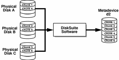
Figure 2-2 shows a striped metadevice built from three slices (disks).
When DiskSuite stripes data from the metadevice to the slices, it writes data from chunk 1 to Disk A, from chunk 2 to Disk B, and from chunk 3 to Disk C. DiskSuite then writes chunk 4 to Disk A, chunk 5 to Disk B, chunk 6 to Disk C, and so forth.
The interlace value sets the size of each chunk. The total capacity of the striped metadevice d2 equals the number of slices multiplied by the size of the smallest slice. (If each slice in the example below were 2 Gbytes, d2 would equal 6 Gbytes.)
Figure 2-2 Striped Metadevice Example
Concatenated Stripe
A concatenated stripe is a striped metadevice that has been expanded by concatenating additional slices (stripes).
Concatenated Stripe Conventions
-
Why would I use a concatenated stripe?
This is the only way to expand an existing striped metadevice.
Note -
If you use DiskSuite Tool to drag multiple slices into an existing striped metadevice, you are given the optional of making the slices into a concatenation or a stripe. If you use the metattach(1M) command to add multiple slices to an existing striped metadevice, they must be added as a stripe.
-
How do I set up the interlace value for a concatenated stripe?
At the stripe level, using either the Stripe Information window in DiskSuite Tool, or the -i option to the metattach(1M) command. Each stripe within the concatenated stripe can have its own interlace value. When you create a concatenated stripe from scratch, if you do not specify an interlace value for a particular stripe, it inherits the interlace value from the stripe before it.
Example -- Concatenated Stripe
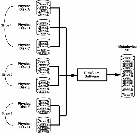
Figure 2-3 illustrates that d10 is a concatenation of three stripes.
The first stripe consists of three slices, Disks A through C, with an interlace of 16 Kbytes. The second stripe consists of two slices Disks D and E, and uses an interlace of 32 Kbytes. The last stripe consists of a two slices, Disks F and G. Because no interlace is specified for the third stripe, it inherits the value from the stripe before it, which in this case is 32 Kbytes. Sequential data chunks are addressed to the first stripe until that stripe has no more space. Chunks are then addressed to the second stripe. When this stripe has no more space, chunks are addressed to the third stripe. Within each stripe, the data chunks are interleaved according to the specified interlace value.
Figure 2-3 Concatenated Stripe Example
Simple Metadevices and Starting Blocks
When you create a simple metadevice of more than one slice, any slice except the first skips the first disk cylinder, if the slice starts at cylinder 0. For example, consider this output from the metastat(1M) command:
# metastat d0

d0: Concat/Stripe
    Size: 3546160 blocks
    Stripe 0: (interface: 32 blocks)
        Device              Start Block  Dbase
        c1t0d0s0                   0     No
        c1t0d1s0                   1520  No
        c1t0d2s0                   1520  No
        c1t0d2s0                   1520  No
        c1t1d0s0                   1520  No
        c1t1d1s0                   1520  No
        c1t1d2s0                   1520  No
|
In this example, stripe d0 shows a start block for each slice except the first as block 1520. This is to preserve the disk label in the first disk sector in all of the slices except the first. The metadisk driver must skip at least the first sector of those disks when mapping accesses across the stripe boundaries. Because skipping only the first sector would create an irregular disk geometry, the entire first cylinder of these disks is skipped. This enables higher level file system software (UFS) to optimize block allocations correctly. Thus, DiskSuite protects the disk label from being overwritten, and purposefully skips the first cylinder.
The reason for not skipping the first cylinder on all slices in the concatenation or stripe has to do with UFS. If you create a concatenated metadevice from an existing file system, and add more space to it, you would lose data because the first cylinder is where the data is expected to begin.
Mirrors
A mirror is a metadevice that can copy the data in simple metadevices (stripes or concatenations) called submirrors, to other metadevices. This process is called mirroring data. (Mirroring is also known as RAID level 1.)
A mirror provides redundant copies of your data. These copies should be located on separate physical devices to guard against device failures.
Mirrors require an investment in disks. You need at least twice as much disk space as the amount of data you have to mirror. Because DiskSuite must write to all submirrors, mirrors can also increase the amount of time it takes for write requests to be written to disk.
After you configure a mirror, it can be used just as if it were a physical slice.
You can also use a mirror for online backups. Because the submirrors contain identical copies of data, you can take a submirror offline and back up the data to another medium--all without stopping normal activity on the mirror metadevice. You might want to do online backups with a three-way mirror so that the mirror continues to copy data to two submirrors. Also, when the submirror is brought back online, it will take a while for it to sync its data with the other two submirrors.
You can mirror any file system, including existing file systems. You can also use a mirror for any application, such as a database. You can create a one-way mirror and attach another submirror to it later.
Note -
You can use DiskSuite's hot spare feature with mirrors to keep data safe and available. For information on hot spares, see Chapter 3, Hot Spare Pools.
Mirrors have names like other metadevices (d0, d1, and so forth). For more information on metadevice naming, see Table 1-4. Each submirror (which is also a metadevice) has a unique device name.
Submirrors
A mirror is made of one or more stripes or concatenations. The stripes or concatenations within a mirror are called submirrors. (A mirror cannot be made of RAID5 metadevices.)
A mirror can consist of up to three (3) submirrors. (Practically, creating a two-way mirror is usually sufficient. A third submirror enables you to make online backups without losing data redundancy while one submirror is offline for the backup.)
Submirrors are distinguished from simple metadevices in that normally they can only be accessed by the mirror. The submirror is accessible only through the mirror when you attach it to the mirror.
If you take a submirror "offline," the mirror stops reading and writing to the submirror. At this point, you could access the submirror itself, for example, to perform a backup. However, the submirror is in a read-only state. While a submirror is offline, DiskSuite keeps track of all writes to the mirror. When the submirror is brought back online, only the portions of the mirror that were written (resync regions) are resynced. Submirrors can also be taken offline to troubleshoot or repair physical devices which have errors.
Submirrors have names like other metadevices (d0, d1, and so forth). For more information on metadevice naming, see Table 1-4.
Submirrors can be attached or detached from a mirror at any time. To do so, at least one submirror must remain attached at all times. You can force a submirror to be detached using the -f option to the metadetach(1M) command. DiskSuite Tool always "forces" a mirror detach, so there is no extra option. Normally, you create a mirror with only a single submirror. Then you attach a second submirror after creating the mirror.
Mirror Conventions
-
For maximum data availability. The trade-off is that a mirror requires twice the number of slices (disks) as the amount of data to be mirrored.
-
How many submirrors can a mirror contain?
DiskSuite enables you to create up to a three-way mirror (a mirror of three submirrors). However, two-way mirrors usually provide sufficient data redundancy for most applications, and are less expensive in terms of disk drive costs.
-
Why should I always create a one-way mirror then attach additional submirrors?
This ensures that a mirror resync is performed so that data is consistent in all submirrors.
Example -- Mirrored Metadevice
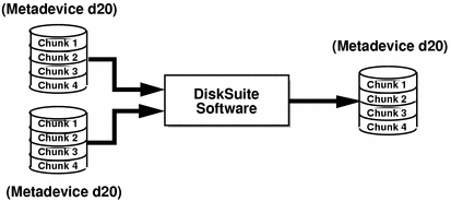
Figure 2-4 illustrates a mirror, d2, made of two metadevices (submirrors) d20 and d21.
DiskSuite software takes duplicate copies of the data located on multiple physical disks, and presents one virtual disk to the application. All disk writes are duplicated; when reading, data only needs to be read from one of the underlying submirrors. The total capacity of mirror d2 is the size of the smaller of the submirrors (if they are not equal sized).
Figure 2-4 Mirror Example
Mirror Options
The following options are available to optimize mirror performance:
-
Mirror read policy
-
Mirror write policy
-
The order in which mirrors are resynced (pass number)
You can define mirror options when you initially create the mirror, or after a mirror has been set up. For tasks related to changing these options, refer to Solstice DiskSuite 4.2.1 User's Guide.
Mirror Resync
Mirror resynchronization is the process of copying data from one submirror to another after submirror failures, system crashes, when a submirror has been taken offline and brought back online, or after the addition of a new submirror.
While the resync takes place, the mirror remains readable and writable by users.
A mirror resync ensures proper mirror operation by maintaining all submirrors with identical data, with the exception of writes in progress.
Note -
A mirror resync is mandatory, and cannot be omitted. You do not need to manually initiate a mirror resync; it occurs automatically.
Full Mirror Resync
When a new submirror is attached (added) to a mirror, all the data from another submirror in the mirror is automatically written to the newly attached submirror. Once the mirror resync is done, the new submirror is readable. A submirror remains attached to a mirror until it is explicitly detached.
If the system crashes while a resync is in progress, the resync is started when the system reboots and comes back up.
Optimized Mirror Resync
During a reboot following a system failure, or when a submirror that was offline is brought back online, DiskSuite performs an optimized mirror resync. The metadisk driver tracks submirror regions and knows which submirror regions may be out-of-sync after a failure. An optimized mirror resync is performed only on the out-of-sync regions. You can specify the order in which mirrors are resynced during reboot, and you can omit a mirror resync by setting submirror pass numbers to 0 (zero). (See "Pass Number" for information.)
A pass number of 0 (zero) should only be used on mirrors mounted as read-only.
Partial Mirror Resync
Following a replacement of a slice within a submirror, DiskSuite performs a partial mirror resync of data. DiskSuite copies the data from the remaining good slices of another submirror to the replaced slice.
Pass Number
The pass number, a number in the range 0-9, determines the order in which a particular mirror is resynced during a system reboot. The default pass number is one (1). Smaller pass numbers are resynced first. If 0 is used, the mirror resync is skipped. A 0 should be used only for mirrors mounted as read-only. Mirrors with the same pass number are resynced at the same time.
Mirror Read and Write Policies
DiskSuite enables different read and write policies to be configured for a mirror. Properly set read and write policies can improve performance for a given configuration.
Table 2-1 Mirror Read Policies|
Read Policy |
Description |
|---|---|
|
Round Robin (Default) |
Attempts to balance the load across the submirrors. All reads are made in a round-robin order (one after another) from all submirrors in a mirror. |
|
Geometric |
Enables reads to be divided among submirrors on the basis of a logical disk block address. For instance, with a two-way submirror, the disk space on the mirror is divided into two equally-sized logical address ranges. Reads from one submirror are restricted to one half of the logical range, and reads from the other submirror are restricted to the other half. The geometric read policy effectively reduces the seek time necessary for reads. The performance gained by this mode depends on the system I/O load and the access patterns of the applications. |
|
First |
Directs all reads to the first submirror. This should be used only when the device(s) comprising the first submirror are substantially faster than those of the second submirror. |
Table 2-2 Mirror Write Policies
|
Write Policy |
Description |
|---|---|
|
Parallel (Default) |
A write to a mirror is replicated and dispatched to all of the submirrors simultaneously. |
|
Serial |
Performs writes to submirrors serially (that is, the first submirror write completes before the second is started). The serial option specifies that writes to one submirror must complete before the next submirror write is initiated. The serial option is provided in case a submirror becomes unreadable, for example, due to a power failure. |
Mirror Robustness
DiskSuite cannot guarantee that a mirror will be able to tolerate multiple slice failures and continue operating. However, depending on the mirror's configuration, in many instances DiskSuite can handle a multiple-slice failure scenario. As long as multiple slice failures within a mirror do not contain the same logical blocks, the mirror continues to operate. (The submirrors must also be identically constructed.)
Consider this example:
Figure 2-5 Mirror Robustness Example
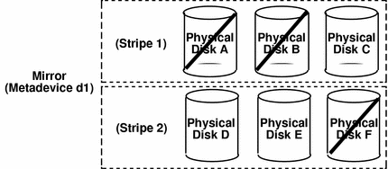
Mirror d1 consists of two stripes (submirrors), each of which consists of three identical physical disks and the same interlace value. A failure of three disks, A, B, and F can be tolerated because the entire logical block range of the mirror is still contained on at least one good disk.
If, however, disks A and D fail, a portion of the mirror's data is no longer available on any disk and access to these logical blocks will fail.
When a portion of a mirror's data is unavailable due to multiple slice errors, access to portions of the mirror where data is still available will succeed. Under this situation, the mirror acts like a single disk that has developed bad blocks; the damaged portions are unavailable, but the rest is available.
RAID5 Metadevices
RAID is an acronym for Redundant Array of Inexpensive Disks (or Redundant Array of Independent Disks).
There are seven RAID levels, 0-6, each referring to a method of distributing data while ensuring data redundancy. (RAID level 0 does not provide data redundancy, but is usually included as a RAID classification because it is the basis for the majority of RAID configurations in use.)
DiskSuite supports:
-
RAID level 0 (concatenations and stripes)
-
RAID level 1 (mirror)
-
RAID level 5 (striped metadevice with parity information)
RAID level 5 is striping with parity and data distributed across all disks. If a disk fails, the data on the failed disk can be rebuilt from the distributed data and parity information on the other disks.
Within DiskSuite, a RAID5 metadevice is a metadevice that supports RAID Level 5.
DiskSuite automatically initializes a RAID5 metadevice when you add a new slice, or resyncs a RAID5 metadevice when you replace an existing slice. DiskSuite also resyncs RAID5 metadevices during rebooting if a system failure or panic took place.
RAID5 metadevices have names like other metadevices (d0, d1, and so forth). For more information on metadevice naming, see Table 1-4.
RAID5 Metadevice Conventions
-
Why should I use RAID5 metadevices?
RAID5 metadevices need fewer disks for data redundancy than mirrors, and therefore can cost less than a mirrored configuration.
-
What is the minimum number of slices that a RAID5 metadevice must have?
Three (3).
-
Is there a maximum number of slices a RAID5 metadevice can have?
No. The more slices a RAID5 metadevice contains, however, the longer read operations take when a slice fails. (By the nature of RAID5 metadevices, write operations are always slower.)
-
How do I expand a RAID5 metadevice?
By concatenating slices to the existing part of a RAID5 metadevice.
-
When I expand a RAID5 metadevice, are the new slices included in parity calculations?
Yes.
-
What are the limitations to RAID5 metadevices?
You cannot use a RAID5 metadevice for root (/), /usr, and swap, or existing file systems.
-
Is there a way to recreate a RAID5 metadevice without having to "zero out" the data blocks?
Yes. You can use the metainit(1M) command with the -k option. (There is no equivalent within DiskSuite Tool.) The -k option recreates the RAID5 metadevice without initializing it, and sets the disk blocks to the OK state. If any errors exist on disk blocks within the metadevice, DiskSuite may begin fabricating data. Instead of using this option, you may want to initialize the device and restore data from tape. See the metainit(1M) man page for more information.
Example -- RAID5 Metadevice
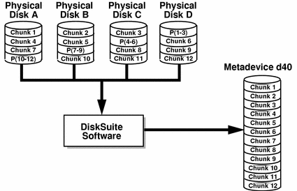
Figure 2-6 shows a RAID5 metadevice, d40.
The first three data chunks are written to Disks A through C. The next chunk that is written is a parity chunk, written to Drive D, which consists of an exclusive OR of the first three chunks of data. This pattern of writing data and parity chunks results in both data and parity spread across all disks in the RAID5 metadevice. Each drive can be read independently. The parity protects against a single disk failure. If each disk in this example were 2 Gbytes, the total capacity of d40 would be 6 Gbytes. (One drive's worth of space is allocated to parity.)
Figure 2-6 RAID5 Metadevice Example
Example -- Concatenated (Expanded) RAID5 Metadevice
Figure 2-7 shows an example of an RAID5 metadevice that initially consisted of four disks (slices). A fifth disk has been dynamically concatenated to the metadevice to expand it.
Figure 2-7 Expanded RAID 5 Metadevice Example
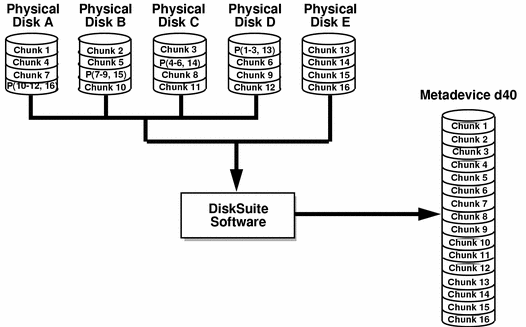
The parity areas are allocated when the initial RAID5 metadevice is created. One column's (slice's) worth of space is allocated to parity, although the actual parity blocks are distributed across all of the original columns to avoid hot spots. When you concatenate additional slices to the RAID, the additional space is devoted entirely to data; no new parity blocks are allocated. The data on the concatenated slices is, however, included in the parity calculations, so it is protected against single device failures.
Concatenated RAID5 metadevices are not suited for long-term use. Use a concatenated RAID5 metadevice unitl it is possible to reconfigure a larger RAID5 metadevice and copy the data to the larger metadevice.
Note -
When you add a new slice to a RAID5 metadevice, DiskSuite "zeros" all the blocks in that slice. This ensures that the parity will protect the new data. As data is written to the additional space, DiskSuite includes it in the parity calculations.
UFS Logging or Trans Metadevices
UFS Logging
UFS logging is the process of writing file system "metadata" updates to a log before applying the updates to a UFS file system.
UFS logging records UFS transactions in a log. Once a transaction is recorded in the log, the transaction information can be applied to the file system later.
At reboot, the system discards incomplete transactions, but applies the transactions for completed operations. The file system remains consistent because only completed transactions are ever applied. Because the file system is never inconsistent, it does not need checking by fsck(1M).
A system crash can interrupt current system calls and introduce inconsistencies into a UFS. If you mount a UFS without running fsck(1M), these inconsistencies can cause panics or corrupt data.
Checking large file systems takes a long time, because it requires reading and verifying the file system data. With UFS logging, UFS file systems do not have to be checked at boot time because the changes from unfinished system calls are discarded.
DiskSuite manages UFS logging through trans metadevices.
UFS Logging Conventions
-
Can UFS logging improve performance?
UFS logging saves time when you reboot after a failure, because it eliminates the need to run the fsck(1M) command on file systems.
-
What are the drawbacks to UFS logging?
If the log fills up, performance can decrease because the UFS must empty the log before writing new information into it.
-
What versions of Solaris work with UFS logging?
UFS logging can only be used with Solaris 2.4 or later releases.
-
Which file systems cannot be logged?
Non-UFS file systems as well as the root (/) file system cannot be logged.
Trans Metadevices
A trans metadevice is a metadevice that manages UFS logging. A trans metadevice consists of two devices: a master device and a logging device.
A master device is a slice or metadevice that contains the file system that is being logged. Logging begins automatically when the trans metadevice is mounted, provided the trans metadevice has a logging device. The master device can contain an existing UFS file system (because creating a trans metadevice does not alter the master device), or you can create a file system on the trans metadevice later. Likewise, clearing a trans metadevice leaves the UFS file system on the master device intact.
A logging device is a slice or metadevice that contains the log. A logging device can be shared by several trans metadevices. The log is a sequence of records, each of which describes a change to a file system.
A trans metadevice has the same naming conventions as other metadevices: /dev/md/dsk/d0, d1 ...,d2, and so forth. (For more information on metadevice naming conventions, see Table 1-4.)
Trans Metadevice Conventions
-
How do I use a trans metadevice?
After a trans metadevice is configured, it can be used just as if it were a physical slice. A trans metadevice can be used as a block device (up to 2 Gbytes) or a raw device (up to 1 Tbyte). A UFS file system can be created on the trans metadevice if the master device doesn't already have a file system.
A logging device or a master device can be a physical slice or a metadevice. For reliability and availability, however, use mirrors for logging devices. A device error on a physical logging device could cause data loss. You can also use mirrors or RAID5 metadevices as master devices.
-
How much disk space does a logging device need?
A minimum of 1 Mbyte. (Larger logs permit more simultaneous file-system transactions.) The maximum log size is 1 Gbyte. 1 Mbyte worth of log per 1 Gbyte of file system is a recommended minimum. 1 Mbyte worth of log per 100 Mbyte of file system is a recommended "average." Unfortunately, there are no hard and fast rules. The best log size varies with an individual system's load and configuration. However, a log larger than 64 Mbytes will rarely be used. Fortunately, log sizes can be changed without too much work.
-
Which file systems should I log?
Generally, log your largest UFS file systems and the UFS file system whose data changes most often. It is probably not necessary to log small file systems with mostly read activity.
-
Which file systems should always have separate logs?
All logged file systems can shared the same log. For better performance, however, file systems with the heaviest loads should have separate logs.
You must disable logging for /usr, /var, /opt, or any other file systems used by the system during a Solaris upgrade or installation when installing or upgrading software on a Solaris system.
-
Place logs on mirrors, unused slices, or slices that contain the state database replicas. A device error on a physical logging device (a slice) can cause data loss.
-
What if no slice is available for the logging device?
You can still configure a trans metadevice. This may be useful if you plan to log exported file systems when you do not have a spare slice for the logging device. When a slice is available, you only need to attach it as a logging device. For instructions, see Solstice DiskSuite 4.2.1 User's Guide.
-
Can a logging device be shared between trans metadevices?
Yes, a logging device can be shared between file systems, though heavily-used file systems should have their own logging device. The disadvantage to sharing a logging device is that certain errors require that all file systems sharing the logging device must be checked with the fsck(1M) command.
Example -- Trans Metadevice
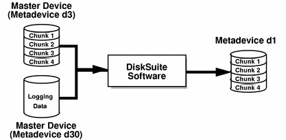
Figure 2-8 shows a trans metadevice, d1,consisting of a mirrored master device, d3, and a mirrored logging device, d30
Figure 2-8 Trans Metadevice Example
Example -- Shared Logging Device
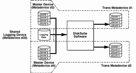
Figure 2-9 shows two trans metadevices, d1 and d2, sharing a mirrored logging device, d30. Each master device is also a mirrored metadevice, as is the shared logging device.
Figure 2-9 Shared Log Trans Metadevice Example
- © 2010, Oracle Corporation and/or its affiliates
