| Sun Fire X4500/X4540 Servers Diagnostics Guide |
| C H A P T E R 8 |
|
Initial Inspection of the Server |
This chapter includes the following topics:
Use the following flowchart as a guideline for using this guide to troubleshoot the Sun Fire Sun Fire X4500/X4540 Servers server.
FIGURE 8-1 Troubleshooting Flowchart

Use the following general guidelines when you begin troubleshooting.
1. Collect initial service visit information, from the service-call paperwork or onsite personnel, about the following items:
2. Document the exisiting server settings before you make any changes.
Record the BIOS version, software version and server serial numbers. Check the product notes to view issues associated with the server hardware and software.
3. Adjust the exisiting server settings to correct the problem.
If possible, make one change at a time in order to isolate potential problems. Use this method to maintain a controlled environment and reduce troubleshooting.
4. Note the changes made and results of any change you make.
Include any errors or informational messages.
5. Check for potential device conflicts before you add a new device.
6. Check for version dependencies, especially with third-party software.
7. If the problem is not evident, continue with the next section, Troubleshooting Power Problems.
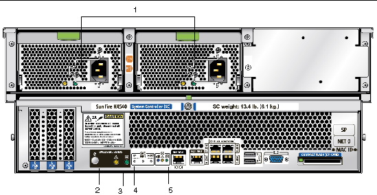
1. Check that AC power cords are attached firmly to the server’s power supplies and to the AC sources.
Use of the cable clamps will ensure that the AC power cords are attached to the server’s power supplies. FIGURE 8-3 shows AC power cords on the rear panel.
2. Check that the server covers, including hard disk drive access cover, system controller cover, and fan access cover are firmly in place.
Refer to the cover labels. An intrusion switch on the system controller shuts the server down when the hard disk drive access cover is removed.
3. Investigate the conditions that can trigger an automatic shutdown sequence:
A power-off sequence is initiated by a request from either of the following items:
| Note - Any power supply that is out of spec causes a reset, but only power supplies that remain out of spec for more than 100 mS cause a shutdown. |
Improperly set controls and loose or improperly connected cables are common causes of problems with hardware components.
To perform a visual inspection of the external system:
1. Inspect the front panel LEDs for indications of component malfunction.
FIGURE 8-2 shows the front panel controls and indicators. TABLE 8-1 describes the controls and indicators.
FIGURE 8-2 Sun Fire X4540 Server Front Panel LEDs

2. Inspect the back panel LEDs for indications of component malfunction.
FIGURE 8-3 shows the rear panel features. TABLE 8-2 describes each feature.
FIGURE 8-3 Sun Fire X4540 Server Rear Panel LEDs
For additional LED locations and descriptions, see Identifying Status and Fault LEDs.
3. Verify that nothing in the server environment is blocking air flow or making a contact that could short out power.
4. If the problem is not evident, continue with the next section, Internal Inspection of the Server.
To perform a visual inspection inside the server:
1. Shut down the server, from main power to standby power mode.
Choose one of the following methods, using a non-conducting ballpoint pen or stylus. See FIGURE 8-4.
After main power is off, the Power/OK LED on the front panel blinks once every three seconds, indicating that the server is in standby power mode.
FIGURE 8-4 Sun Fire X4540 Server Front Panel
2. Remove the component covers, including hard disk drive cover, system controller cover, and fan cover, as required.
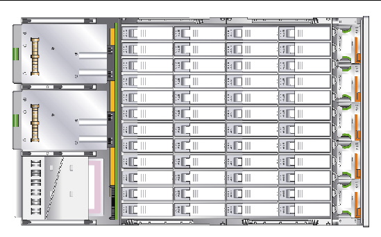
FIGURE 8-5 shows the server internal components. For instructions on removing the component covers, refer to the Sun Fire X4540 Server Service Manual, 819-4359.
FIGURE 8-5 Sun Fire X4540 Server Internal Components
3. Inspect the internal status indicator LEDs, which can indicate component malfunction.
For LED locations and descriptions, see Internal Status Indicator LEDs and DIMM Fault LEDs.
4. Verify that there are no loose or improperly seated components.
5. Verify that all cable connectors inside the system are firmly and correctly attached to their appropriate connectors.
6. Verify that any after-factory components are qualified and supported.
For a list of supported PCI cards and DIMMs, refer to the Sun Fire X4540 Server Service Manual, 819-4359.
7. Check that the installed DIMMs comply with the supported DIMM population rules and configurations, as described in Chapter 10, Troubleshooting DIMM Problems.
8. Replace the component covers.
9. To restore main power mode to the server (all components powered on), use a non-conducting ballpoint pen or stylus to press and release the Power button on the server front panel. See FIGURE 8-4.
When main power is applied to the full server, the Power/OK LED next to the Power button lights and remains lit.
10. If the problem with the server is not evident, you can try viewing the power-on self test (POST) messages and BIOS event logs during system startup. Continue with Viewing Event Logs.
| Sun Fire X4500/X4540 Servers Diagnostics Guide | 819-4363-12 |
Copyright © 2009 Sun Microsystems, Inc. All rights reserved.