Introduction to the Sun Fire X4540 Server
|
This chapter introduces you to the Sun Fire X4540 Server and describes important features.
The following information is covered in this chapter:
X4540 Server Features
The Sun Fire X4540 server is a mid-level, modular, rack-optimized server in the Sun x64 product family. The family platform includes servers engineered for AMD Opteron CPUs. The Sun Fire X4540 server deploys into commercial server markets in a slide-mounted, horizontally-biased enclosure for rack cabinet installations, primarily in datacenter locations.
The Sun Fire X4540 server includes an extensive set of reliability, availability, and serviceability (RAS) features, such as hot-pluggable and redundant hard disk drives (when RAID 1 is used), and hot-swappable fans, and power supplies. The servers also provide an integrated lights out management (ILOM) service processor function that includes remote boot and remote software upgrades.
TABLE 8-1 summarizes the features of the Sun Fire X4540 server.
TABLE 8-1 Summary of X4540 Server Features
|
Feature or Component
|
Sun Fire X4540 Server
|
|
CPU
|
Two AMD Opteron 2000 Series CPUs, Quad-Core, 2-socket configuration
|
|
Processor BIOS
|
8-Mb Flash with LPC interface.
|
|
Memory
|
16 DIMM slots (8 per processor), up to 4 GB per DIMM (64 GB per system). 128-bit DDR2 interface (2x64-bit data+2x8-bit ECC)
|
|
Hard disk drives (HDDs)
|
Up to forty-eight 3.5 SATA drives, of 250/500/750GB/1TB capacity each (over 48 TB total system capacity), supports SATA II, 3.0Gb/s.
|
|
Service Processor
|
Integrated Lights Out Manager (ILOM).
Refer to the ILOM documentation (see the Integrated Lights Out Manager (ILOM) Administration Guide (819-0280).
|
|
RAID options
|
RAID is configured through software.
|
|
Network I/O
|
- Four 10/100/1000BASE-T Gigabit Ethernet ports (RJ-45 connectors)
- One 10/100BASE-T Ethernet net management port (RJ-45 Connector) NET MGT
- One RS-232 serial port (RJ-45 Connector) SER MGT (see Serial Port)
|
|
Serial Port
|
RS-232 serial interface, RJ45 connector
Console only, no modem support (no RI, PPP)
Connected to ILOM by default
Default parameters
- 9600 baud
- 8 data bits
- No parity
- 1 stop bit
- No flow control
|
|
PCI I/O
|
Three PCI-e slots, 8-laneslot (x8), LSI SAS 1068E.
- Six SATA Controllers on IO Board, LSI SATA controller x 6. Each controller supports 8 HDDs
- 51.5 mm (2.5 inches) maximum height
- 169.3 mm (6.7 inches) maximum length
|
|
Other I/O
|
- Four USB 2.0 ports
- One VGA video port
- Compact flash card slot
|
|
Power
|
1500 W DC max output per power supply, two bays, 1+1 redundancy, hot-swappable.
1130 W AC max system input power = 3856 BTU/hr = 0.321 tons of air conditioning, 200-240 VAC.
|
|
Fans
|
Five fan modules; also additional fans in each power supply.
Cooling is front-to-back forced air. Hot swappable, Variable speed, 7500 R.P.M. max, Top loading, Fault/OK LEDs,1.8A / 18W, SATA connector.
The SP software controls the fan speed and detects fan failure.
Operation terminates if a fan tray is removed.
NOTE: Do not operate the system with a fan removed for more than 60 seconds.
|
Exterior Features, Controls, and Indicators
This section describes the features, controls, and indicators on the front and rear panels of the Sun Fire X4540 server.
Front Panel
FIGURE 8-1 shows the front panel. FIGURE 8-2 shows a close up of the controls and indicators.
FIGURE 8-1 Sun Fire X4540 Server Front Panel Features

FIGURE 8-2 Sun Fire X4540 Server Front Panel Controls and Indicators
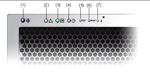
Graphic showing the X4540 server front panel controls and indicators.
TABLE 8-2 Sun Fire X4540 Server Front Panel Controls and Indicators
|
Number
|
Name
|
Color
|
Description
|
1
|
Locate button/LED
|
White

|
Operators can turn this LED on remotely to help them locate the server in a crowded server room. Press to turn off.
|
2
|
Service action required
|
Amber

|
On - When service action is required.
|
3
|
Power/Operation
|
Green

|
Steady - Power is on.
Blink - Standby power is on but main power is off.
Off - Power is off.
|
4
|
System power button
|
Gray
|
To power on main power for all the server components.
|
5
|
Top failure LED
|
Amber
|
On - HDD or fan fault.
|
6
|
Rear failure LED
|
Amber
|
On - Power supply or system controller fault (service is required).
|
7
|
Over temperature LED
|
Amber
|
On - When system is over temperature.
|
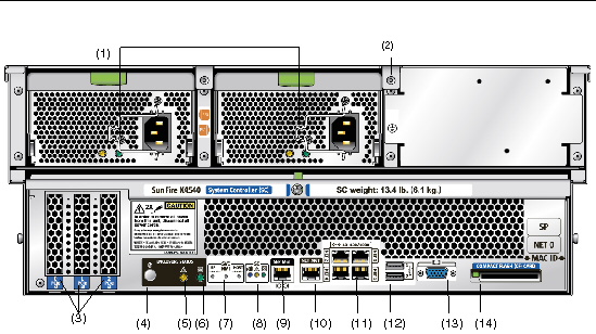
FIGURE 8-3 shows the rear panel features.
FIGURE 8-3 Sun Fire X4540 Server Rear Panel
 [ D ]
[ D ]
TABLE 8-3 Rear Panel Features
|
#
|
Name
|
Description
|
|
1
|
AC power connectors
|
Verify that the PS LEDs are green. Each power supply has its own AC connector with a clip to secure its power cable.
|
|
2
|
Chassis ground
|
Connect grounding straps here.
|
|
3
|
0 PCI-e, 1 PCI-e, 2 PCI-e
|
Slots for three PCI-e cards.
|
|
4
|
Locate button/LED

|
White Operators can turn this LED On remotely to help then locate the server in a crowded server room. Press to turn off.
|
|
5
|
Fault LED

|
Amber - When on, service action required.
Steady - Power is On.
Off - Power is Off.
|
|
6
|
OK LED

|
Green - Service action allowed.
When On, service action is required.
Blink - Standby power is On but main power is Off.
|
|
7
|
SVC Service buttons
|
SP - Reset Service Processor.
NMI - Non-Maskable Interrupt dump. Sends an NMI to the CPU. Used for debugging only.
Host - Reset Host Bus Adapter.
Do not use these buttons unless instructed by Sun service personnel. To operate these buttons, insert a stylus or a straightened paper clip into the recess.
|
|
8
|
SC - System controller status LEDs
|
Blue - Ready to remove.

Amber - Fault, service action required.

Green - Operational, no action required.

|
|
9
|
SER MGT
|
Serial management port (serial connection to service processor).
|
|
10
|
NET MGT (S)
|
Net management and service processor port.
|
|
11
|
10/100/1000
|
GigabitEthernet ports connect server to Ethernet.
|
|
12
|
USB connectors
|
Connect USB devices.
|
|
13
|
Video connector
|
Connect video monitor.
|
|
14
|
Compact flash (CF) card
|
Insert compact flash card devices.
|
Disk Drive and Fan Tray LEDs
FIGURE 8-4 shows the location of the internal LEDs.
FIGURE 8-5 shows a close-up view of the disk drive and fan trays, including the symbols that identify the LEDs.
FIGURE 8-4 Disk Drive Locations

FIGURE 8-5 Disk Drive and Fan Tray LEDs

About Reliability, Availability, and Serviceability Features
Reliability, availability, and serviceability (RAS) are aspects of a system’s design that affect its ability to operate continuously and to minimize the time necessary to service the system. Together, reliability, availability, and serviceability features provide for near continuous system operation.
Reliability refers to a system’s ability to operate continuously without failures and to maintain data integrity. System availability refers to the percentage of time that a system remains accessible and usable. Serviceability relates to the time it takes to restore a system to service following a system failure.
To deliver high levels of reliability, availability and serviceability, the Sun Fire X4540 Server system offers the following features:
- Hot-pluggable disk drives
- Redundant, hot-swappable power supplies
- Environmental monitoring and fault protection
- Integrated Lights Out Management (ILOM), Sun’s remote management capability
- Support for disk and network multipathing with automatic failover capability
- Error correction and parity checking for improved data integrity
- Easy access to all internal replaceable components
- Full in-rack serviceability by extending the slides
Hot-Pluggable and Hot-Swappable Components
Sun Fire X4540 Server hardware is designed to support hot-pluggable and
hot-swappable components. Hot-plugging and hot-swapping are cost-effective solutions that provides increased system availability and continuous serviceability for business-critical computing environments, by providing the ability to:
- Remove or replace a failed or failing component while the system is operating without service disruption.
- Increase storage capacity dynamically to handle larger work loads and improve system performance.
Hot-pluggable Components Overview
The Sun Fire X4540 server hot-plug technology allows a component to be added, upgraded, or replaced while the system is running without affecting hardware integrity.
Hot-plugging provides the ability to physically add, remove, or replace a hard disk drive while the system is running, and other hard disks in the system provide continuous service. When a hot-pluggable component is removed from the Sun Fire X4540 server, it must be taken offline from the operating system first, but does not require that the server be powered off.
On the Sun Fire X4540 server, you can hot-plug the following components.
TABLE 8-4 Sun Fire X4540 Hot-Pluggable Devices
|
Component
|
Part Number
|
|
250 GB SATA 3.5 Hard Disk Drive
|
541-1467
|
|
500 GB SATA 3.5 Hard Disk Drive
|
541-1468
|
|
750 GB SATA 3.5 Hard Disk Drive
|
540-7244
|
|
1 TB SATA 3.5 Hard Disk Drive
|
540-7507
|
For instructions on hot-plugging components, see the following:
- cfgadm Command in cfgadm Command.
- cfgadm(1M) (See the cfgadm(1M) man page for more information.)
Hot-swappable Components Overview
A hot-swappable component can be removed or replaced without affecting software integrity. A component that is removed does not need to be taken offline from the operating system first.
On the Sun Fire X4540 server, you can hot-swap the following components:
TABLE 8-5 Sun Fire X4540 Hot-Swappable Devices (Partial List)
|
Component
|
Part Number
|
|
Power supply (type A205)
|
300-1787
|
|
Fan module
|
541-0458
|
For more information about updating the Sun Fire X4540 Server, product updates, or for the most up-to-date list of replaceable components, refer to the Sun Fire X4540 Server Service Manual (819-4359), and the Sun Fire X4540 Server Product Notes (820-4869).
| Sun Fire X4500/X4540 Servers Administration Guide
|
819-6562-17
|
   
|
Copyright © 2009 Sun Microsystems, Inc. All rights reserved.