Specifications and Connectors
|
This chapter provides the specifications and connector Pin-outs for the Netra CP32x0 ARTM-10G.
This chapter contains the following topics:
B.1 Specifications
This section provides mechanical, electrical, environmental, and other relevant specifications.
B.1.1 Physical Dimensions
The Netra CP32x0 ARTM-10G is a 6U (233.35 mm) height board with 80 mm in depth for standard applications. It complies with IEEE 1101.11 mechanical standards, as required by the PICMG 2.0 Revision 3.0 specification. The Netra CP32x0 ARTM-10G is keyed to conform to the PICMG 2.10, “Keying of ATCA Boards and Backplanes” specification.
B.1.2 Power Requirements
The Netra CP32x0 ARTM-10G derives all power from the front ATCA node board. The front board must provide the following voltages: 3.3V/5V/+12V/12V.
The power consumption of the ARTM is limited to 25W maximum. The 3.3V power to the management port is limited to 200ma and the current limit-set point for the 12V payload power is 2.5a.
B.1.3 Environmental Specifications and Compliance
The environmental specifications for the Netra CP32x0 ARTM-10G assembly are presented in TABLE B-1.
TABLE B-1 Environmental Specifications
|
Specification
|
Value
|
|
Operating Temperature (airflow 5.0 CFM)
|
0˚C ~ 55 ˚
|
|
Operating Temperature (airflow 2.0 CFM)
|
0˚C ~ 23 ˚
|
|
Storage Temperature
|
-40 ˚~ 85 ˚
|
|
Operating Temperature Gradient
|
11 ˚/H (max)
|
|
Storage Temperature Gradient
|
20 ˚/H (max)
|
|
Shipping Temperature Gradient
|
20 ˚/H (max) *1
|
|
Operating Humidity
|
8 % ~ 80 %
|
|
Storage Humidity
|
5 % ~ 95 %
|
|
Shipping Humidity
|
5 % ~ 95 % *1
|
|
Wet bulb Maximum Temperature
|
27 ˚
|
|
Condensation
|
No condensation
|
|
Atmospheric Pressure and Altitude
|
Operating: 0 ~ 3,000 m
Shipping: 0 ~ 12,000 m
|
|
Operating Shock
|
See PICMG 3.0 specification, Regulatory guidelines.
|
|
Operating Vibration
|
See PICMG 3.0 specification, Regulatory guidelines.
|
|
RoHS
|
6 of 6 compliant
|
B.1.4 Pressure Drop Versus Airflow
A thermal simulation model of the ARTM was constructed to analyze the pressure drop of the ARTM at incremental airflow conditions. System integrators may use these results as part of the selection criteria for the host chassis.
FIGURE B-1 Pressure Drop Simulation Model
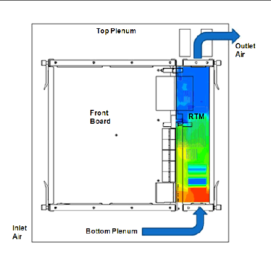
TABLE B-2 Pressure Drop Versus Inlet Air Speed
|
Wind Speed
|
Inlet Pressure (N/M2)
|
Pressure Drop (N/M2/psf)
|
|
0 CFM (0m/s)
|
0
|
0/0
|
|
1 CFM (0.274m/s)
|
1.4
|
1.4/0.03
|
|
2 CFM (0.548m/s)
|
4
|
4/0.087
|
|
3 CFM (0.822m/s)
|
7.6
|
7.6/0.166
|
|
4 CFM (1.096m/s)
|
12.1
|
12.1/0.264
|
|
5 CFM (1.37m/s)
|
17.6
|
17.6/0.384
|
|
6 CFM (1.644m/s)
|
24
|
24/0.523
|
|
7 CFM (1.918m/s)
|
31.2
|
31.2/0.68
|
|
8 CFM (2.192m/s)
|
39.4
|
39.4/0.86
|
|
9 CFM (2.466m/s)
|
48.3
|
48.3/1.05
|
|
10 CFM (2.74m/s)
|
58.1
|
58.1/1.266
|
B.1.5 NEBS Compliance
NEBS certifications are performed by the integrator at a system level (chassis, ATCA, AMC shelf managers, etc.). The ARTM module will not preclude the system from passing NEBS.
B.1.6 Electromagnetic Compliance
The board is designed and implemented to minimize electromagnetic emissions, susceptibility, and electrostatic discharge effects. The ARTM carries the certifications shown in TABLE B-3.
TABLE B-3 EMC Emission Compliance
|
Certification
|
Compliance
|
|
US: FCC 47 CFR Part 15 Class A
|
Yes, Class A emissions requirements (USA)
|
|
Canada: ICES 003 Class A
|
Yes Class A Digital Apparatus emissions (Canada)
|
|
Japan: VCCI Class A
|
Yes Class A ITE emissions requirements (Japan)
|
|
Europe Commercial: EN 55022:1994 Class A
|
Yes, Class A ITE emissions requirements (EU)
|
|
Europe Commercial: EN 55024:1998 Class A
|
Immunity for ITE equipment
|
|
Europe Commercial: EN 61000-4-2,3,5,6,8,11: 2001
|
EMC Electrostatic discharge immunity
|
|
Europe Commercial: EN 61000-4-4: 2000 (Limits for harmonic current emissions)
|
Yes
|
|
Europe Commercial: EN 61000-3-2,3
|
Yes, Limits for harmonic current emissions
|
|
Europe Telecom Carrier: EN 300-386 v1.3.3 April 2005
|
Requirements for Telecom Network Equipment - Non-Telco Centers
|
|
Europe CE Mark
|
Yes
|
|
Australia: AS/NZS 3548 C-Tick
|
Yes, Class A ITE emissions requirements (Australia)
|
|
Korea: MIC
|
Yes
|
|
Taiwan: BSMI
|
Yes
|
B.2 Connectors and PIN Assignments
This section provides position and PIN-out details of all connectors available on the Netra CP32x0 ARTM-10G.
FIGURE B-2 Netra CP32x0 ARTM-10G Connectors
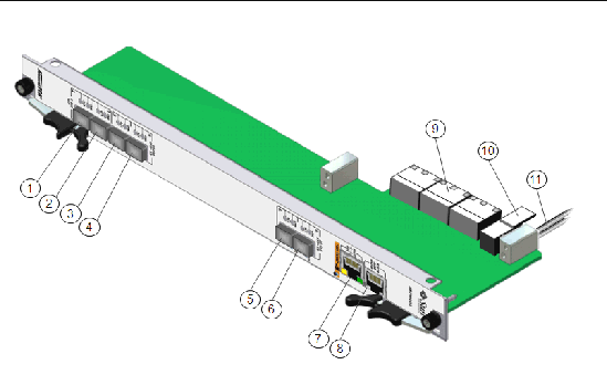
TABLE B-4 Connector Port Identification and Location
|
1
|
1GbE SFP
|
7
|
10/100/1000 Mb management port
|
|
2
|
1GbE SFP
|
8
|
Serial console port
|
|
3
|
10GbE SFP+
|
9
|
Zone 3 Connectors
|
|
4
|
10GbE SFP+
|
10
|
Power connector
|
|
5
|
10GbE SFP+
|
11
|
RTM alignment PIN
|
|
6
|
10GbE SFP+
|
|
|
B.2.1 1GbE SFP Ethernet Ports
Ports 1 and 2 are shipped without SFP modules. The Netra CP32x0 ARTM-10G can be populated with either single mode or multimode variety, using LC connectors.
TABLE B-5 1GbE SFP Connector Characteristics
|
XSFP-SW-2GB-Z
|
(Short Reach) SFP Transceiver for the Express Module
|
|
SG-XSWCS-CU-SFPL-Z
|
1000BASE-T Copper SFP transceivers
|
B.2.2 10GbE SFP+ Ethernet Ports
Ports 3, 4, 5 and 6 are shipped without SFP+ modules. The Netra CP32x0 ARTM-10G can be populated with either single mode or multimode variety, using LC connectors.
TABLE B-6 10GbE SFP+ Connector Characteristics
|
X5561A-Z -SR
|
(Short Reach) SFP+ Transceiver for the ExpressModule
|
|
|
10GBASE-SR: Depending on fiber quality, up to 300 meters for high bandwidth multimode fiber
|
B.2.3 10/100/1000 Mb Management Port
The Netra CP32x0 ARTM-10G provides a 1GbE management port on the faceplate via R-J45 jack (port 7). The port is wired as pass through to the front ATCA carrier via the J32/P32 Zone-3 connector.
FIGURE B-3 10/100/1000 Mb Management Port PIN Location
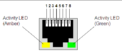
TABLE B-7 10/100/1000 Management Port PIN Locations
|
PIN
|
Signal Name
|
PIN
|
Signal Name
|
|
1
|
DA+
|
5
|
DC-
|
|
2
|
DA-
|
6
|
DB-
|
|
3
|
DB+
|
7
|
DD+
|
|
4
|
DC+
|
8
|
DD-
|
B.2.4 Serial Console Management Port
Port 8 is a low-profile RJ-45 connector jack that provides RS-232 signaling. The port is wired as pass through to the front ATCA carrier via the J32/P32 Zone-3 connector.
FIGURE B-4 Serial Console Management Port PIN Locations
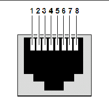
TABLE B-8 Serial Console Management Port PIN Locations
|
PIN
|
Signal Name
|
PIN
|
Signal Name
|
|
1
|
RTS
|
5
|
GND
|
|
2
|
DTR
|
6
|
RXD
|
|
3
|
TXD
|
7
|
DSR
|
|
4
|
GND
|
8
|
CTS
|
B.2.5 Zone 3 Connectors
The Netra CP32x0 ARTM-10G routes all of the I/O signals to the front ATCA board through the Zone 3 connector complex consisting of connections P31, P32 and P33. These “P” connectors mate with “J” connectors located on the ATCA board. All of these connectors use a 3-PIN per column type, available from Tyco Electronics Corporation (http://www.tycoelectronics.com), part number 1469183-1.
ATCA blades designed to connect with the Netra CP32x0 ARTM-10G should use a Tyco (or equivalent receptacle): 1469081-1, Receptacle 3-pair 10 column HM-Zd.
| Note - The ARTM connector PIN-outs are presented from the point of view of the ATCA board, such that: “TX” refers to ATCA as the signal source, and ARTM as the signal receiver. And “RX” refers to the ATCA board as signal receiver, and ARTM as signal source.
|
FIGURE B-5 Zone 3 Connector Port PIN Locations
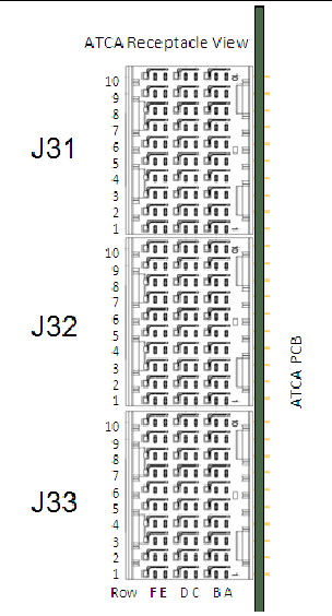
B.2.5.1 Connector P31, 10GbE XAUI PIN Assignments
The Netra CP32x0 ARTM-10G P31 connector information is in TABLE B-9 and TABLE B-10.
TABLE B-9 Connector P31, 10GbE XAUI PIN Assignments
|
Row
|
Interface
|
A
|
B
|
C
|
D
|
E
|
F
|
|
1
|
XAUI
|
XAUI_0_TX1+
|
XAUI_0_TX1-
|
XAUI_0_RX0+
|
XAUI_0_RX0-
|
XAUI_0_TX0+
|
XAUI_0_TX0-
|
|
2
|
XAUI
|
XAUI_0_RX2+
|
XAUI_0_RX2-
|
XAUI_0_TX2+
|
XAUI_0_TX2-
|
XAUI_0_RX1+
|
XAUI_0_RX1-
|
|
3
|
XAUI
|
XAUI_1_TX0+
|
XAUI_1_TX0-
|
XAUI_0_RX3+
|
XAUI_0_RX3-
|
XAUI_0_TX3+
|
XAUI_0_TX3-
|
|
4
|
XAUI
|
XAUI_1_RX1+
|
XAUI_1_RX1-
|
XAUI_1_TX1+
|
XAUI_1_TX1-
|
XAUI_1_RX0+
|
XAUI_1_RX0-
|
|
5
|
XAUI
|
XAUI_1_TX3+
|
XAUI_1_TX3-
|
XAUI_1_RX2+
|
XAUI_1_RX2-
|
XAUI_1_TX2+
|
XAUI_1_TX2-
|
|
6
|
XAUI
|
|
|
|
|
XAUI_1_RX3+
|
XAUI_1_RX3-
|
|
7
|
|
|
|
|
|
|
|
|
8
|
|
|
|
|
|
|
|
|
9
|
|
|
|
|
|
|
|
|
10
|
|
|
|
|
|
|
|
TABLE B-10 Connector P31, 10GbE XAUI Signal Descriptions
|
XAUI_0_TX
|
XAUI Port 0 TX signals - optional Zone 3 Extended Options overlay
|
|
XAUI_0_RX
|
XAUI Port 0 RX signals - optional Zone 3 Extended Options overlay
|
|
XAUI_1_TX
|
XAUI Port 1 TX signals - optional Zone 3 Extended Options overlay
|
|
XAUI_1_RX
|
XAUI Port 1 RX signals - optional Zone 3 Extended Options overlay
|
B.2.5.2 Connector P32, Management Infrastructure PIN Assignments
The Netra CP32x0 ARTM-10G P32 connector information is in TABLE B-11 and TABLE B-12.
TABLE B-11 Connector P32, Management Infrastructure PIN Assignments
|
Row
|
Interface
|
A
|
B
|
C
|
D
|
E
|
F
|
|
1
|
MDIO
|
XAUI_MDIO
|
XAUI_MDC
|
|
|
|
|
|
2
|
RS-232
|
|
|
|
|
SR0_RTS
|
SR0_DTR
|
|
3
|
RS-232
|
|
|
|
|
SR0_TXD
|
SR0_RXD
|
|
4
|
RS-232
|
|
|
|
|
SR0_DSR
|
SR0_CTS
|
|
5
|
|
|
|
|
|
|
|
|
6
|
LAN
|
LAN0_A+
|
LAN0_A-
|
LAN0_CTV
|
LAN0_CTV
|
LAN0_B+
|
LAN0_B-
|
|
7
|
LAN
|
LAN0_C+
|
LAN0_C-
|
ACT_LED#
|
LINK_LED#
|
LAN0_D+
|
LAN0_D-
|
|
8
|
|
|
|
|
|
|
|
|
9
|
|
|
|
|
|
|
|
|
10
|
|
|
|
|
|
|
|
TABLE B-12 Connector P32, Management Infrastructure Signal Descriptions
|
LAN0
|
10/100/1000BASE-T signals
|
|
LAN0_CTV
|
10/100/1000BASE-T transformer Center Tap signal, which could be used to terminate center tap of transformers, if they are placed on an ARTM. This signal is applicable if Ethernet PHY is located on ATCA blade, while GE transformers are located on an ARTM.
|
|
ACT_LED#
|
LAN 0 (Management) activity indicator signal for LED (active low)
|
|
LINK_LED#
|
LAN 0 (Management) LINK indicator signal for LED (active low)
|
|
SR0_...
|
RS-232 Serial Signals, Transmit, Receive, Clear To Send, Request To Send, Data Terminal Ready, Data Set Ready.
|
|
XAUI_MDIO
|
XAUI MDIO signal - optional Zone 3 Extended Option overlay. Together with MDC, this serial bus may be used to access registers within the Media Access Controller (MAC) for purposes of configuration or to retrieve PHY status.
|
|
XAUI_MDC
|
XAUI MDC signal - optional Zone 3 Extended Option overlay.
|
B.2.5.3 Connector P33, Management Infrastructure PIN Assignments
The Netra CP32x0 ARTM-10G P33 connector information is in TABLE B-13 and TABLE B-14.
TABLE B-13 Connector P33, PCIe and Miscellaneous ARTM PIN Assignments
|
Row
|
Interface
|
A
|
B
|
C
|
D
|
E
|
F
|
|
1
|
PCIe
|
PETx0+
|
PETx0-
|
PERx0+
|
PERx0-
|
FCLKA+
|
FCLK+
|
|
2
|
PCIe
|
PETx1+
|
PETx1-
|
PERx1+
|
PERx1-
|
|
|
|
3
|
PCIe
|
PETx2+
|
PETx2-
|
PERx2+
|
PERx2-
|
|
|
|
4
|
PCIe
|
PETx3+
|
PETx3-
|
PERx3+
|
PERx3-
|
|
|
|
5
|
PCIe
|
PETx4+
|
PETx4-
|
PERx4+
|
PERx4-
|
|
|
|
6
|
PCIe
|
PETx5+
|
PETx5-
|
PERx5+
|
PERx5-
|
|
|
|
7
|
PCIe
|
PETx6+
|
PETx6-
|
PERx6+
|
PERx6-
|
|
|
|
8
|
PCIe
|
PETx7+
|
PETx7-
|
PERx7+
|
PERx7-
|
|
PCI_RST#
|
|
9
|
Misc
|
NC
|
NC
|
NC
|
NC
|
ARTM#
|
PCI_CFG
|
|
10
|
Misc.
|
NC
|
NC
|
NC
|
NC
|
PS0#
|
Enable#
|
TABLE B-14 Connector P33, PCIe and Miscellaneous ARTM Signal Descriptions
|
PETx...
|
PCI-Express transmit differential pair signals
|
|
PERx...
|
PCI-Express receive differential pair signals
|
|
FCLKA
|
Fabric clock, as defined in AMC.0 specification. Intended to be used for PCI-Express 100 MHz spread spectrum clock.
|
|
PCI_RST#
|
PCI-Express reset signal. Logic low shall reset PCI-Express switch and PCI-Express interfaces that are behind it. The Netra CP32x0 ARTM-10G asserts logic ground to this signal.
|
|
ARTM#
|
ARTM# signal is grounded by the Netra CP32x0 ARTM-10G to indicate a MMC controller is present (see AMC.0 specification.) The ATCA implementation shall include a 10Kohm pull-up resistor to management power on the ATCA. In this way, an ATCA is able to detect non-intelligent vs. intelligent ARTMs.
|
|
PCI_CFG
|
PCI-Express bus configuration signal. It shall be grounded on ARTMs that use a single x8 PCI-Express bus and pulled up on the ATCA with 10Kohm resistor to management power. On ARTMs that expect two x4 PCI-Express buses this pin will float (not be connected). Two x4 PCI Express buses are intended for ARTM implementations that desire to avoid PCI-Express switch in order to reduce latency. The Netra CP32x0 ARTM-10G asserts logic ground to this signal.
|
|
PS0#
|
Active low ARTM present signal.PS0# shall be tied to logic GND on the ATCA blade. PS0# (Connector J33) and PS1# (Connector J30) shall be connected through a diode on the Netra CP32x0 ARTM-10G, exactly as defined in AMC.0 specification. PS1# is last mate on Power connector and PS0# is on the opposite end of the set of connectors. Logic low on PS1# indicates that ARTM is present and fully inserted.
|
|
Enable#
|
When low indicates to ARTM that it is fully inserted and that MMC can start execution, Logic high shall keep MMC in reset state. This signal shall have a pull-up resistor as indicated in AMC.0 specification.
|
B.2.6 Connector P30, ARTM Power PIN Assignment
The Netra CP32x0 ARTM-10G derives 12V and the 3.3V stand-by voltages from the ATCA front board via the P30 connector. The P30 connector assignments also include the IPMI-L interface, PS1#. The ARTM converts the main 12V payload power into 1.2V, 1.5V, 2.5V and 3.3V by using the DC-DC converters.
The Netra CP32x0 ARTM-10G adheres to the following maximum power ratings:
- Mean power: 25 watts
- Peak Power: 26 watts
- Standard Deviation of power from mean power: 0.25 watts
The Netra CP32x0 ARTM-10G connects to ATCA blades that use the Metral® 89096-xxx from FCI (www.fciconnect.com).
The Netra CP32x0 ARTM-10G P33 connector information is in TABLE B-15 and TABLE B-16.
FIGURE B-6 J30/P30 Receptacle and Connector
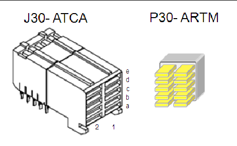
The Netra CP32x0 ARTM-10G mates to the connector with a customized connector that features staggered pin lengths to enforce optimal mating sequence for hot plug:
- First mate: ground, power
- Second mate: all signals.
- Last mate: presence signals PS0# and PS1#
| Note - The ARTM power connector J30 PIN-out is presented from the point of view of the ATCA board.
|
TABLE B-15 P30, ARTM Power PIN Header Assignment
|
Row
|
Interface
|
1
|
2
|
Pin Length
|
|
e
|
Pwr
|
PS1#
|
NC
|
short
|
|
d
|
Pwr
|
+12V PP
|
+12V PP
|
long
|
|
c
|
IPMI
|
IPMI_SCL_L
|
IPMI_SDA_L
|
medium
|
|
b
|
Pwr
|
Logic_GND
|
+3.3V MP
|
long
|
|
a
|
Pwr
|
Logic_GND
|
Shelf_GND
|
long
|
TABLE B-16 Connector P30, ARTM Power PIN Signal Descriptions
|
PS1#
|
Active low ARTM present signal. PS1# shall be pulled up to 3.3V Management Power on the ATCA blade. PS0# (Connector J33) and PS1# (Connector J30) shall be connected through a diode on the Netra CP32x0 ARTM-10G, exactly as defined in AMC.0 specification. PS1# is last mate on Power connector and PS0# is on the opposite end of the set of connectors. Logic low on PS1# indicates that ARTM is present and fully inserted.
|
|
IPMI_SCL_L
|
IPMI bus clock signal, as defined in AMC.0 specification. ARTM shall have a pull-up resistor for this signal as indicated in AMC.0 specification.
|
|
IPMI_SDA_L
|
IPMI bus data signal, as defined in AMC.0 specification. ARTM shall have a pull-up resistor for this signal as indicated in AMC.0 specification.
|
|
12VPP
|
12V Payload Power, enabled after successful e-Keying, following AMC.0 specification. ARTM shall meet requirements posted for payload power in AMC specification.
|
|
3.3V_MP
|
3.3V Management Power. ARTM shall meet requirements posted for management power in AMC.0 specification.
|
|
Shelf_GND
|
Frame/Chassis Safety Ground
|
|
Logic_GND
|
(Logic 0vdc). Logic Ground- Common return for Management Power Payload Power, reference potential for single ended logic signaling, and shielding for differential pair signals in the AMC Connector.
|
| Netra CP32x0 10GbE Advanced Rear Transition Module, Dual Port User’s Guide
|
820-3150-10
|
    |
Copyright © 2008 Sun Microsystems, Inc. All Rights Reserved.


