| C H A P T E R 2 |
|
Installing and Removing the ARTM |
This chapter contains procedures for unpacking, installing, and removing the Netra CP32x0 10GbE Advanced Rear Transition Module, Dual Port (ARTM-10G).
This chapter contains the following topics:
Before installing the Netra CP32x0 ARTM-10G, check the ARTM’s part number to ensure that the correct ARTM is being installed into the system. For information on identifying the ARTM, see Section 1.5, Part Number and Serial Number Labels.
The following paragraphs provide important information to ensure compatibility and safety of the ARTMs, other components, and the system.

|
Caution - When a system is plugged in, energy hazards are present on the midplane. Do not reach into the enclosure. |

|
Caution - Electrostatic discharge (ESD) can damage electronic components. Use an antistatic wrist strap and a conductive foam pad when installing or upgrading any components. |
After removing the component from its protective wrapper or from the system, place the component flat on a grounded, static-free surface (and, in the case of a board, component side up). Do not slide the component over any surface.
If an ESD station is not available, you can avoid damage resulting from ESD by wearing an antistatic wrist strap (available at electronics stores) that is attached to an active electrical ground. Note that a system chassis might not be grounded if it is unplugged.

|
Caution - Dangerous voltages, capable of causing death, are present in this equipment. Use extreme caution when handling, testing, and adjusting equipment. |
If the shipping carton is damaged upon receipt, request that the carrier’s agent be present during the unpacking and inspection of the equipment.
1. Unpack the equipment from the shipping carton.
2. Refer to the packing list and verify that all items are present.
3. Save the packing material for storing and reshipping of equipment.
4. Avoid touching areas of integrated circuitry.
Static discharge can damage circuits.
5. After removing the product from the packaging, check for any obvious physical damage.
6. Disconnect the chassis from the main power supply before you install the ARTM.
The Netra CP32x0 ARTM-10G can be installed into an ATCA shelf (chassis) with a midplane made for front- and rear-board installations. The ARTM must be installed in the slot directly behind the host ATCA node board. These back-to-back slots have common PINs to enable passing of signals via the Zone 3 connector complex.
The Netra CP32x0 ARTM-10G is designed to comply with UL60950-1, and is intended to be used with similarly tested AdvancedTCA products that have user documentation detailing installation of an Advanced Mezzanine Card (AMC) module accessories.
Be sure to validate that the chassis and the ARTM slot are cable of providing the ARTM the maximum power requirements of 25W current draw.
The Netra CP32x0 ARTM-10G was tested and qualified to operate with the following Sun Netra ATCA host blade servers:
The Netra CP32x0 ARTM-10G is designed to operate with similarly tested AdvancedTCA products.
ARTMs can be damaged when improperly handled. Please read and follow the guidelines in this section to protect your equipment.
Installation persons are urged to use an antistatic wrist strap and a conductive foam pad when installing or upgrading a system. See Section 2.1.1, Take Antistatic Precautions.
Bent PINs or loose components can cause damage to the ARTM, host board, the backplane, or other system components. Carefully inspect your ARTM and the backplane for both PIN and component integrity before installation. Our manufacturers take significant steps to ensure there are no bent PINs on the backplane or connector damage to the products prior to leaving our factory. Bent PINs caused by improper installation or by products with damaged connectors could void the warranty for the backplane, boards, and modules.
If a system contains one or more crushed PINs, power off the system and contact your local sales representative to schedule delivery of a replacement chassis assembly.
During operation, to preserve compliance with applicable standards and regulations for electromagnetic interference (EMI), all front and rear openings on the chassis or board faceplates must be filled with an appropriate card or covered with a filler panel. If the EMI barrier is open, devices might cause or be susceptible to excessive interference.
Your ARTM is electrically designed for hot-swap insertion within a fully powered chassis. However hot-swap removal is not supported.

|
Caution - Powering down or removing a board before the operating system or other software running on the board has been properly shut down can cause corruption of data or file systems. |
Prior to board removal, terminate applications or operating systems running on the board. When this task is complete, use the shelf manager to manually shut down (activate/deactivate) the ATCA board, which in turn shuts down the ARTM.
There is a BLUE LED on the rear faceplate. This LED is under software control. When the BLUE LED:
Hot-swap compliant components may be installed while the system is powered on. If a module is not hot-swap compliant, you should remove power to the slot or system before installing the component.
Prevent possible damage to components by verifying the proper slot usage for your configuration. See Section 2.1.3, Use a Compatible Chassis and Slot.
In most cases, electronic keying (e-Keying) will prevent power on of a module in an incompatible slot. However, as an extra precaution, you should be familiar with the slot purpose.
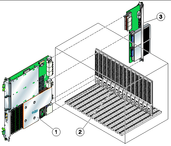
This section describes the procedure for installing the ARTM in a chassis. See FIGURE 2-1 for an example of installing a node board and ARTM into a chassis.
Before you install your ARTM, read all cautions, warnings, and instructions presented in the following sections:
FIGURE 2-1 Installing a Node Board and ARTM Into an ATCA Chassis

|
Netra ATCA node board (also known as blade server) installed from front |
|
|
1. Take the necessary antistatic precautions while unpacking and handling the ARTM and system.
2. At the back of the system, choose a compatible slot for the ARTM.
ARTMs must be installed in-line behind the accompanying host board. For example, if the accompanying host board is going to be installed in slot 3, its ARTM must be installed at the back of the system in slot 3.
3. Remove the slot filler panel from the selected host board slot, if necessary.
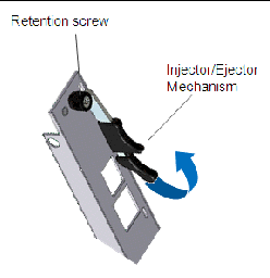
4. Prepare the module by loosening the locking screws and opening the injector/ejector latch at the top of the module as shown in FIGURE 2-2.
FIGURE 2-2 Injector/Ejector Latch and Locking Screw

5. Look into the enclosure to verify correct alignment of the rails in the guides.
6. Align the edges of the module with the card-cage rail guides in the appropriate slot.
7. Taking care to keep the module aligned in the guides, while holding the module handles, apply equal and steady pressure to slide the module in until the injector/ejector mechanism engages the retention bars.

|
Caution - Do not exert unnecessary pressure on the faceplate. |
8. Position your thumbs at the top and bottom of the module; simultaneously push in the module and rotate the injector/ejector mechanisms inward to their closed position to seat and secure the ARTM.

|
Caution - Do not force the ARTM into the slot. |
9. Tighten the two module retention screws to secure the module into the chassis.
10. Power on the system, if necessary.
Refer to your system manual for instructions on correctly powering on the system. Once power is applied to the chassis, the internal MMC controller runs a self-test that runs for approximately 10 seconds. Upon a successful power up self-test, the BLUE LED (hotswap) will blink then turn off, indicating that the module has been placed in operation.
The Netra CP32x0 ARTM-10G is loaded with fcode and firmware prior to shipping.
All fcode and firmware code is stored in a single EEPROM Flash device located on the ARTM. The code provides the ATCA CPU instructions for operating the Sun Multithreaded 10GbE Networking Technology located on the ARTM.
When updates are available, new releases are offered online to improve the functionality or performance of the ARTM.
After you install the ARTM, determine if any updates are available, and upgrade the firmware on your ARTM.
For detailed upgrading instructions, refer to the Netra CP32x0 Advanced Rear Transition Module Product Notes (820-3261), available at the following web site:
http://docs.sun.com/app/docs/prod/cp32x0.10gbee?l=en#hic
The Netra CP32x0 ARTM-10G ARTM is hot-swappable and can be removed from the chassis without powering down its associated host board. This section describes the hot-swap procedure for removing a module from a chassis.
Before you remove your module, read all cautions, warnings, and instructions presented in Section 2.2.4, Understand Hotswap.
If the chassis is not hot-swap compliant, remove power to the slot or system before removing the ARTM.
|
1. Loosen the locking screws on the module.
2. Visually inspect the BLUE LED.
It will illuminate a steady, non-blinking BLUE color when the module is properly prepared for removal.
3. Rotate the top ejector handle to the half way (HW) position.
4. If you need to manually shut down applications, execute the following command from the shelf manager.
When the module has been deactivated, the BLUE LED will illuminate steady.
5. When the BLUE LED is steady, extract the module by pulling on the module handles.
6. Carefully remove the module from the chassis.
7. If the slot is to remain empty, install a filler panel in the slot.
This section provides instructions for verifying the installation of the Netra CP32x0 ARTM-10G.
|
2. When the banner appears, press the Stop-A key sequence to interrupt the boot process and display the OpenBoot (ok) prompt.
3. List the network devices on your system, as in the following example.
Usually /pci@0/pci@0/pci@8 or /pci@0/pci@0/pci@9 corresponds to PCIe slots, so look at those devices first. Also, the ARTM is usually the only device that will display four ports.
| Note - If you do not see the device listed, check that the ARTM is properly seated. If necessary, reinstall the ARTM. |
4. Use the .properties command to display a list of device properties.
Checking the .properties output of a device is the surest way of identifying the ports on the ARTM. For this ARTM, your output will be similar to the following.
5. Type the following when you are done looking at the .properties values:
|
1. Inspect the BLUE hotswap LED on the ARTM.
If the module is installed correctly, the LED will not be illuminated.
2. Open a Linux console window from the host board.
This command displays a list of PCI devices containing Ethernet in the description, such as the following example.
The host board and the ARTM use the same four-port Ethernet controller. If these are installed correctly, the output will show eight Sun Ethernet instances.
|
After verifying the ARTM installation, perform a reconfiguration boot on your system.
Copyright © 2008 Sun Microsystems, Inc. All Rights Reserved.