| Sun Netra X6270 M2 Server Module Service Manual |
| A P P E N D I X D |
|
Memory Module (DIMM) Reference |
When replacing or upgrading a DIMM on the Sun Netra X6270 M2 server module, see the following sections:
The Sun Netra X6270 M2 server module supports a variety of DIMM configurations that can include single-rank (SR) DIMMs, dual-rank (DR) DIMMs, or quad-rank (QR) DIMMs. When replacing or adding memory modules to the Sun Netra X6270 M2 server module, you should consider the following:
For details, see DIMM and CPU Physical Layout.
For details, see DIMM Population Rules.
For details, see DIMM Rank Classification Labels.
For details, see Error Correction and Parity
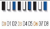
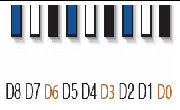
The physical layout of the DIMMs and CPUs on a Sun Netra X6270 M2 server module is shown in FIGURE D-1.
FIGURE D-1 CPU and DIMM Physical Layout

The DIMM population rules for Oracle’s Sun Netra X6270 M2 server module are as follows:
1. Do not populate any DIMM socket next to an empty CPU socket. Each processor contains a separate memory controller.
2. Each CPU can support a maximum of:
3. Populate DIMMs by location according to the following rules:
For example, populate D8/D5/D2 first; then D7/D4/D1 second; and finally, D6/D3/D0. See FIGURE D-1.
Note that QR DIMMs are supported only in white sockets if adjacent blue socket contains a QR DIMM.
4. For maximum performance, apply the following rules:
DIMMs come in a variety of ranks: single, dual, or quad. Each DIMM is shipped with a label identifying its rank classification. TABLE D-2 identifies the corresponding rank classification label shipped with each DIMM.
The server’s processor provides parity protection on its internal cache memories and error-correcting code (ECC) protection of the data. The system can detect and log the following types of errors:
Advanced ECC corrects up to 4 bits in error on nibble boundaries, as long as they are all in the same DRAM. If a DRAM fails, the DIMM continues to function.
Refer to the Oracle Integrated Lights Out Manager (ILOM) 3.0 Documentation Collection for information on how to access the error log.
| Sun Netra X6270 M2 Server Module Service Manual | 821-0939-10 |
Copyright © 2010, Oracle and/or its affiliates. All rights reserved.