ILOM Platform Features for the Sun Blade X6270 M2 Server Module
|
ILOM 3.0 operates on many platforms, supporting features that are common to all platforms. Some ILOM 3.0 features belong to a subset of platforms and not to all. This chapter describes the features that are specific to the Sun Blade X6270 M2 Server Module.
For detailed information about ILOM features that are common to all server platforms, see the ILOM 3.0 Documentation Collection, as described in ILOM 3.0 Common Feature Set Documentation Collection.
ILOM features discussed in this chapter, which are specific to the Sun Blade X6270 M2 Server Module, are as follows:
Supported Server Firmware
TABLE 2-1 identifies the ILOM and BIOS firmware versions that are supported on the Sun Blade X6270 M2 Server Module.
TABLE 2-1 Supported Platform Firmware
|
ILOM SP Version
|
Host BIOS Version
|
ILOM Chassis Monitoring Module (CMM) Firmware
|
Applicable Hardware
|
|
3.0.14.12
|
08.05.01.14
|
C10CMM-SW3.2.2-WEB (r57573-3.0.10.15.b-build2010_29) or SW4.0 (r58226-3.0.12.10-build2010_33)
|
Sun Blade X6270 M2 Server Module
|
|
3.0.9.15.a
|
08.02.01.05
|
3.0.6.11.b (r48988) (or subsequent release)
|
Sun Blade X6270 M2 Server Module
|
For information about how to update the firmware on your server, refer to the ILOM 3.0 Common Feature Set Documentation Collection at:
http://docs.sun.com/app/docs/prod/int.lights.mgr30#hic
Hardware Management Pack for Single Server Management
The Sun Server Hardware Management Pack (Hardware Management Pack) from Oracle provides tools to help you manage and configure your Oracle servers from the host operating system. To use these tools, you must install the Hardware Management Pack software on your server. After installing the Hardware Management Pack software, you will be able to perform the following server management tasks described in TABLE 2-2.
TABLE 2-2 Hardware Managemen t Pack - Server Management Tasks
|
Server Management Task
From Host OS*
|
Hardware Management Pack Implementation
|
Tool
|
|
Monitor Oracle hardware with host IP address
|
Use the Hardware Management Agent and the associated Simple Network Management Protocol (SNMP) Plugins at the operating-system level to enable in-band monitoring of your Oracle hardware. This in-band monitoring functionality enables you to use your host operating system IP address to monitor your Oracle servers without the need of connecting the ILOM management port to your network.
|
Host OS-level
management tool
|
|
Monitor storage devices, including RAID arrays
|
Use the Server Storage Management Agent at the operating-system level to enable in-band monitoring of the storage devices configured on your Oracle servers. The Server Storage Management Agent provides an operating-system deamon that gathers information about your server’s storage devices such as hard disk drives (HDDs) and RAID arrays, and sends this information to the ILOM service processor. The Storage Monitoring features in ILOM enable you to view and monitor the information provided by the Server Storage Management Agent. You can access the Storage Monitoring features in ILOM from the command-line interface (CLI).
|
ILOM 3.0 CLI
Storage Monitoring features
|
|
Configure BIOS CMOS settings, device boot order, and some SP settings
|
Use the biosconfig CLI tool from the host operating system to configure your Oracle x86 servers BIOS CMOS settings, device boot order, and some service processor (SP) settings.
|
Host OS-level
biosconfig CLI
|
|
Query, update, and validate firmware versions on supported SAS storage devices
|
Use the fwupdate CLI tool from the host operating system to query, update, and validate firmware versions on supported storage devices such as SAS host bus adapters (HBAs), embedded SAS storage controllers, LSI SAS storage expanders, and disk drives (spinning media and flash drives).
|
Host OS-level
fwupdate CLI
|
|
Restore, set, and view ILOM configuration settings
|
Use the ilomconfig CLI tool from the host operating system to restore ILOM configuration settings, as well as to view and set ILOM properties that are associated with network management, clock configuration, and user management.
|
Host OS-level
ilomconfig CLI
|
|
View or create RAID volumes on storage drives
|
Use the raidconfig CLI tool from the host operating system to view and create RAID volumes on storage drives that are attached to RAID controllers, including storage arrays.
|
Host OS-level
raidconfig CLI
|
|
Use IPMItool to access and manage Oracle servers
|
Use the open source command-line IPMItool from the host operating system to access and manage your Oracle servers via the IPMI protocol.
|
Host OS-level
command-line IMPItool
|
|
|
View Support Matrix and Download Hardware Management Pack Software
Refer to the following table to view the support matrix for the Hardware Management Pack software or to download the Hardware Management Pack software.
Hardware Management Pack Documentation
For instructions for installing the management pack software or using its components, see the following Hardware Management Pack documentation:
- Sun Server Hardware Management Pack 2.0 User’s Guide (821-1609)
- Sun Server Management Agent 2.0 User’s Guide (821-1601)
- Sun Server CLI Tools and IPMItool 2.0 User's Guide (821-1600)
For additional details about how to use the Storage Monitoring features in ILOM, see Chapter 4 of the Oracle Integrated Lights Out Manager (ILOM) 3.0 Feature Updates and Release Notes (820-7329).
For additional details about accessing and managing your server via SNMP or IPMI, see the Oracle Integrated Lights Out Manager (ILOM) 3.0 Management Protocols Reference Guide (820-6413).
ILOM Sideband Management
By default, you connect to the server’s service processor (SP) using the out-of-band network management port (NET MGT). The ILOM sideband management feature enables you to select either the NET MGT port or one of the server’s Gigabit Ethernet ports (NET 0, 1, 2, 3), which are in-band ports, to send and receive ILOM commands to and from the server SP. In-band ports are also called sideband ports.
The advantage of using a sideband management port to manage the server’s SP is that one fewer cable connection and one fewer network switch port is needed. In configurations where numerous servers are being managed, such as data centers, sideband management can represent a significant savings in hardware and network utilization.
You can configure sideband management using either the web interface, the command-line interface (CLI), the BIOS, or IPMI. For special considerations and configuration instructions, see the following sections:
Special Considerations for Sideband Management
When sideband management is enabled in ILOM, the following conditions might occur:
- Connectivity to the server SP might be lost when the SP management port configuration is changed while you are connected to the SP using a network connection, such as SSH, web, or ILOM Remote Console.
- In-chip connectivity between the SP and the host operating system might not be supported by the on-board host Gigabit Ethernet controller. If this condition occurs, use a different port or route to transmit traffic between the source and destination targets instead of using L2 bridging/switching.
- Server host power cycles might cause a brief interruption of network connectivity for server Gigabit Ethernet ports (NET 0, 1, 2, 3) that are configured for sideband management. If this condition occurs, configure the adjacent switch/bridge ports as host ports.
| Note - If the ports are configured as switch ports and participate in the Spanning Tree Protocol (STP), you might experience longer outages due to spanning tree recalculation.
|
 Configure Sideband Management Using the Web Interface Configure Sideband Management Using the Web Interface
|
1. Log in to the ILOM web interface.
2. Select Configuration --> Network.
The Network Settings page appears.
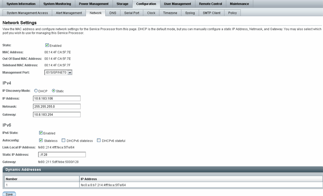
3. In the Network Settings page, do the following:
a. Select the dual-stack IPv4 and IPv6 network settings to obtain and IP address. Refer to the Oracle Integrated Lights Out Manager (ILOM) 3.0 Web Interface Procedures Guide (820-6411) for information about assigning IPv4 and IPv6 network addresses.
b. To select a sideband management port, click the Management Port drop-down list and select the desired management port.
The drop-down list enables you to change to any one of the four Gigabit Ethernet ports, /SYS/MB/NETn, where n is 0 to 3. The SP NET MGT port, /SYS/SP/NET0, is the default.
c. Click Save for the changes to take effect.
 Configure Sideband Management Using the CLI Configure Sideband Management Using the CLI
|
1. Log in to ILOM using the CLI.
| Note - Using a serial connection for this procedure eliminates the possibility of losing connectivity during sideband management configuration changes.
|
2. If you logged in using the serial port, you can assign a static IPv4 and IPv6 network address.
For instructions, see the information about assigning an IP address in the Sun Blade X6270 M2 Server Module Installation Guide (821-0495) or the Oracle Integrated Lights Out Manager (ILOM) 3.0 Web Interface Procedures Guide (820-6411).
3. To show the current port settings, type:
-> show /SP/network
The network properties appear. For example:
/SP/network
    Targets:
    Properties:
        commitpending = (Cannot show property)
        dhcp_server_ip = none
        ipaddress = xx.xx.xx.xx
        ipdiscovery = static
        ipgateway = xx.xx.xx.xx
        ipnetmask = xx.xx.xx.xx
        macaddress = 11.11.11.11.11.86
        managementport = /SYS/SP/NET0
        outofbandmacaddress = 11.11.11.11.11.86
        pendingipaddress = xx.xx.xx.xx
        pendingipdiscovery = static
        pendingipgateway =  xx.xx.xx.xx
        pendingipnetmask =  xx.xx.xx.xx
        pendingmanagementport = /SYS/SP/NET0
        sidebandmacaddress = 11.11.11.11.11.87
        state = enabled
|
In the above output the current active macaddress is the same as the SP’s outofbandmacaddress and the current active managementport is set to the default (/SYS/SP/NET0).
4. To set the SP management port to a sideband port, type the following commands:
-> set /SP/network pendingmanagementport=/SYS/MB/NETn
Where n equals 0, 1, 2, or 3.
-> set commitpending=true
5. To view the change, type:
-> show /SP/network
The network properties appear and show that the change has taken effect. For example:
/SP/network
    Targets:
    Properties:
        commitpending = (Cannot show property)
        dhcp_server_ip = none
        ipaddress = xx.xx.xx.xx
        ipdiscovery = static
        ipgateway = xx.xx.xx.xx
        ipnetmask = xx.xx.xx.xx
        macaddress = 11.11.11.11.11.87
        managementport = /SYS/MB/NETn
        outofbandmacaddress = 11.11.11.11.11.86
        pendingipaddress = xx.xx.xx.xx
        pendingipdiscovery = static
        pendingipgateway =  xx.xx.xx.xx
        pendingipnetmask =  xx.xx.xx.xx
        pendingmanagementport = /SYS/MB/NETn
        sidebandmacaddress = 11.11.11.11.11.87
        state = enabled
|
In the above output the macaddress matches the sidebandmacaddress, and the managementport matches the pendingmanagementport.
 Configure Sideband Management Using the Host BIOS Setup Utility Configure Sideband Management Using the Host BIOS Setup Utility
|
You can access the BIOS Setup Utility screens from the following interfaces:
- Use a USB keyboard, mouse, and VGA monitor connected directly to the server.
- Use a terminal (or terminal emulator connected to a computer) through the serial port on the back panel of the server.
- Connect to the server using the ILOM Remote Console. To use this interface, you must know the IP address of the server.
To configure sideband management using the host BIOS Setup Utility, perform the following steps:
1. Power on or power cycle the server.
2. To enter the BIOS Setup Utility, press the F2 key while the system is performing the power-on self-test (POST).

When BIOS is started, the main BIOS Setup Utility top-level screen appears. This screen provides seven menu options across the top of the screen.
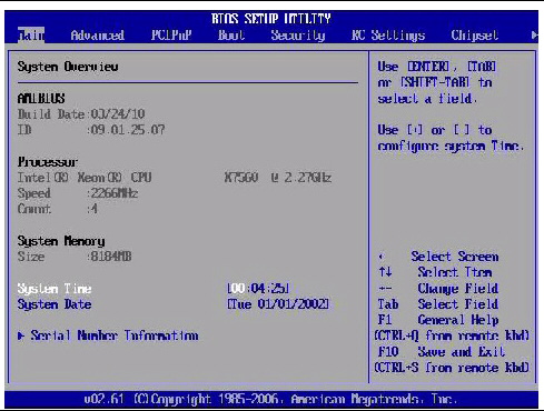
3. In the main screen, select Advanced --> IPMI Configuration.
The IPMI 2.0 Configuration screen appears.
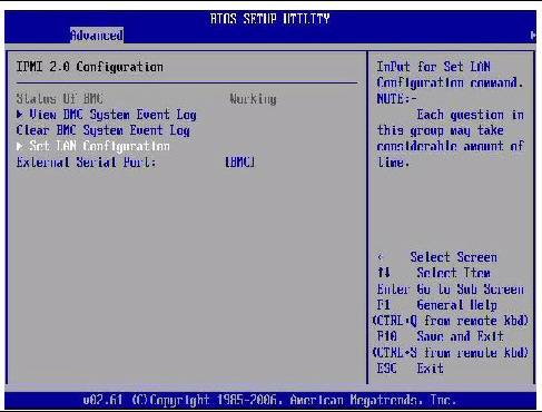
4. In the IPMI 2.0 Configuration screen, select the Set LAN Configuration option.
The LAN Configuration screen appears.
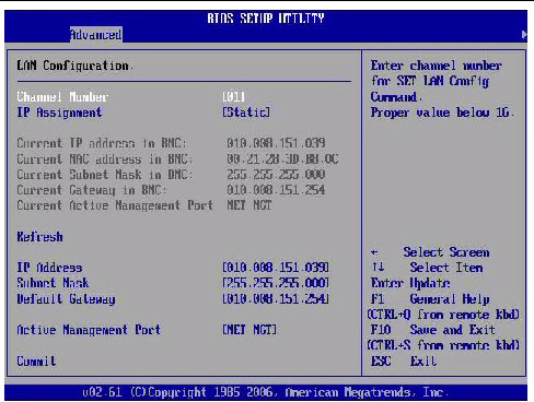
5. In the LAN Configuration screen, do the following:
a. Use the left and right arrow keys to select the IP Assignment option and set it to DHCP.
b. Use the left and right arrow keys to select the Active Management Port option and set the port to a sideband management port (NET0, NET1, NET2, NET3).
The NET MGT port is the default.
c. Select Commit for the change to take effect.
Switch Serial Port Output Between SP and Host Console
You can switch the serial port output of the Sun Blade X6270 M2 Server Module between the SP console (SER MGT) and the host console (COM1). By default, the SP console is connected to the system serial port. This feature is beneficial for Windows kernel debugging, as it enables you to view non-ASCII character traffic from the host console.
You can switch serial port output using either the ILOM web interface or the ILOM command-line interface (CLI). For instructions, see the following sections:

|
Caution - You should set up the network on the SP before attempting to switch the serial port owner to the host server. If a network is not set up, and you switch the serial port owner to the host server, you will be unable to connect using the CLI or web interface to change the serial port owner back to the SP. To change the serial port owner back to the SP, you must use the ILOM Preboot Menu to restore access to the serial port over the network. For more information see the ILOM Preboot Menu information in the Sun Blade X6270 M2 Server Module Service Manual(821-0499).
|
 Switch Serial Port Output Using the Web Interface Switch Serial Port Output Using the Web Interface
|
1. Log in to the ILOM web interface.
2. Select Configuration --> Serial Port.
The Serial Port Settings page appears.
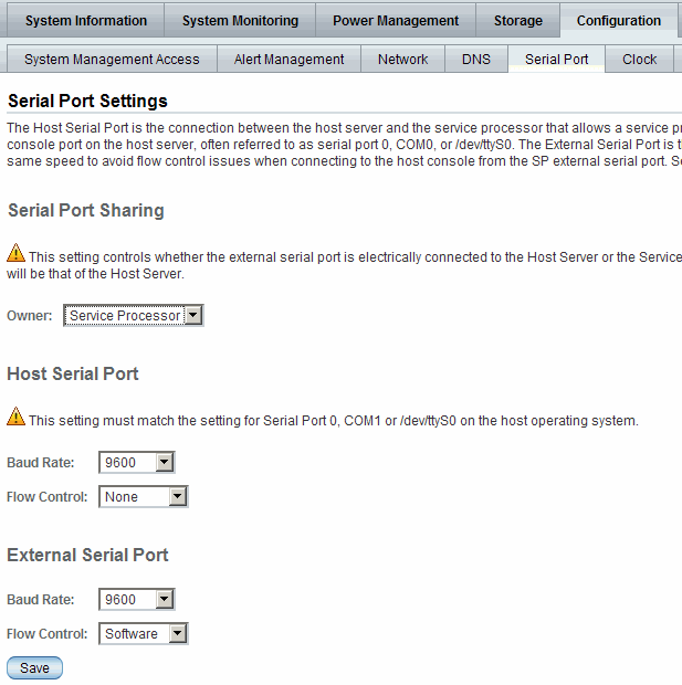
3. To select a serial port owner, click the Owner drop-down list and select the desired serial port owner.
The drop-down list enables you to select either Service Processor or Host Server.
By default, Service Processor is selected.
4. Click Save for your change to take effect.
 Switch Serial Port Output Using the CLI Switch Serial Port Output Using the CLI
|
1. Log in to the ILOM CLI.
2. To set the serial port owner, type:
-> set /SP/serial/portsharing/owner=host
By default, owner=SP.
Clear Server and CMM Faults
When a server component fails, the server generates a component-specific fault that is captured by the ILOM SP. Some faults are cleared automatically when the failed component is replaced, but faults generated for components that are not hot-serviceable have to be cleared manually. You can use either the ILOM web interface or the command-line interface (CLI) to manually clear faults.
For the Sun Blade X6270 M2 Server Module, the following types of faults must be cleared manually after the faulty component is replaced:
- Fabric Expansion Module (FEM) faults
- CPU faults
- Motherboard faults (when motherboard is not replaced)
Other faults captured by the fault management function in ILOM include faults generated by the chassis monitoring module (CMM). These faults occur when other components in the chassis fail, for example:
- CMM faults
- Fan faults
- Power supply faults
- NEM faults
Chassis related faults are not automatically cleared by the system. You must manually clear these faults in the Fault Management function on the ILOM CMM. After you have cleared the faults reported by the CMM, the chassis related faults are then automatically cleared by the system in the Fault Management function on the ILOM SP.
When clearing faults, give consideration to the following:
- When clearing faults for memory DIMMs, note that the DIMM faults can be either system wide (/SYS/MB) or on a per DIMM basis (/SYS/MB/Pn/Dn).
- PCIe faults include /SYS/MB/NETn.
The procedure for clearing a fault differs depending on the type of fault:
- To clear the fault.security.integrity-compromised@/sys/sp fault, replace the server’s top cover and reboot the server’s SP.
- To clear DIMM, CPU, motherboard, and PCIe faults, access the server’s ILOM SP and clear the fault for the failed component.
For information on how to use the ILOM web interface or the CLI to clear server faults, see the Oracle ILOM 3.0 Common Feature Set Documentation Collection at:
http://docs.sun.com/app/docs/prod/int.lights.mgr30#hic
Sensors and Indicators Reference Information
The server includes several sensors that report on hardware conditions. Many of the sensor readings are used to adjust the fan speeds and perform other actions, such as illuminating LEDs and powering off the server.
This section describes the sensors that ILOM monitors for the Sun Blade X6270 M2 Server Module.
The following types of sensors are described:
| Note - For information about how to obtain sensor readings or to determine the state of system indicators in ILOM, see the Oracle Integrated Lights Out Manager (ILOM) 3.0 CLI Procedures Guide (820-6412) and the Oracle Integrated Lights Out Manager (ILOM) 3.0 Web Interface Procedures Guide (820-6411).
|
Temperature Sensors
TABLE 2-3 describes the environmental sensors.
TABLE 2-3 Temperature Sensors
|
Sensor Name
|
Sensor Type
|
Description
|
|
/SYS/MB/T_AMB
|
Temperature
|
Motherboard ambient temperature sensor
|
|
/SYS/T_AMB
|
Temperature
|
Mirror of /SYS/MB/T_AMB
|
|
/SYS/MB/RFEM0/T_AMB
|
Temperature
|
Temperature sensor on FEM
|
Fan Sensors
TABLE 2-5 describes the fan sensors.
TABLE 2-4 Fan Sensors
|
Sensor Name
|
Sensor Type
|
Description
|
|
/SYS/FM[0-5]/F[0-1]/TACH
|
Speed
|
Fan speed sensor
|
|
/SYS/FM[0-5]/ERR
|
Fault
|
Fan module error
|
FEM Sensor
TABLE 2-5 describes the Fabric Expansion Module (FEM) sensor.
TABLE 2-5 FEM Sensor
|
Sensor Name
|
Sensor Type
|
Description
|
|
/SYS/MB/RFEM[0-1]/FAULT
|
Fault
|
Asserts when the FEM fails
|
Power Supply Sensors
TABLE 2-6 describes the power supply sensors.
TABLE 2-6 Power Supply Unit Current, Voltage, and Power Sensors
|
Sensor Name
|
Sensor Type
|
Description
|
|
/SYS/PS[0-1]/PRSNT
|
Presence
|
Power supply presence sensor
|
|
/SYS/PS[0-1]/S[0-1]/V_IN_ERR
|
Fault
|
Power supply input voltage sensor
|
|
/SYS/PS[0-1]/S[0-1]/V_OUT_OK
|
Fault
|
Power supply output voltage fault sensor
|
|
/SYS/VPS
|
Fault
|
Voltage and current monitor
|
Entity Presence Sensors
TABLE 2-7 describes the entity presence sensors. In the table, n designates numbers
0-n.
TABLE 2-7 Presence Sensors
|
Sensor Name
|
Sensor Type
|
Description
|
|
/SYS/HDD[0-3]/PRSNT
|
Entity presence
|
Storage device presence sensor
|
|
/SYS/PS[0-1]/PRSNT
|
Entity presence
|
Power supply presence sensor
|
|
/SYS/PEM[0-1]/PRSNT
|
Entity presence
|
PCI ExpressModule presence sensor
|
|
/SYS/NEM[0-1]/PRSNT
|
Entity presence
|
Network Express Module (NEM) presence sensor
|
|
/SYS/CMM/PRSNT
|
Entity presence
|
Chassis Monitoring Module (CMM) presence sensor
|
|
/SYS/BL[0-9]/PRSNT
|
Entity presence
|
Blade presence sensor
|
|
/SYS/SLOTID
|
Entity presence
|
Blade’s slot ID
|
|
/SYS/MB/P[0-1]/PRSNT
|
Entity presence
|
CPU presence sensor
|
|
/SYS/MB/P[0-1]/D[0-8]/PRSNT
|
Entity presence
|
DIMM presence sensor
|
|
/SYS/MB/RFEM[0-1]/PRSNT
|
Entity presence
|
Fabric Expansion Module (FEM) presence sensor
|
|
/SYS/MB/REM/PRSNT
|
Entity presence
|
RAID Expansion Module (REM) presence sensor
|
System Indicators
TABLE 2-8 describes the system indicators.
TABLE 2-8 System Indicators
|
Sensor Name
|
Description
|
|
/SYS/OK
|
Front panel OK/Power green LED
|
|
/SYS/LOCATE
|
Front panel Locate white LED
|
|
/SYS/SERVICE
|
Front panel Service amber LED
|
|
/SYS/OK2RM
|
Front panel OK To Remove blue LED
|
|
/SYS/HDD[0-3]/OK2RM
|
Storage drive OK To Remove blue LED
|
|
/SYS/HDD[0-3]/SERVICE
|
Storage drive Service amber LED
|
|
/SYS/RFEM[0-1]/SERVICE
|
Storage drive RFEM Service indicator
|
|
/SYS/MB/P[0-1]/SERVICE
|
CPU Service indicator
|
|
/SYS/MB/P[0-1]/D[0-8]/SERVICE
|
DIMM Service indicator
|
SNMP and PET Message Reference Information
This section describes Simple Network Management Protocol (SNMP) and Platform Event Trap (PET) messages that are generated by devices being monitored by ILOM.
SNMP Traps
SNMP Traps are generated by the SNMP agents that are installed on the SNMP devices being managed by ILOM. ILOM receives the SNMP Traps and converts them into SNMP event messages that appear in the event log. For more information about the SNMP event messages that might be generated on your system, see TABLE 2-9.
TABLE 2-9 SNMP Event Messages
|
SNMP Trap Message
|
ILOM Event Message
|
Severity and Description
|
Sensor Name
|
|
Memory SNMP Events
|
|
|
|
sunHwTrapMemoryFault
|
fault.memory.channel.misconfigured
|
Major; A memory component is suspected of causing a fault
|
/SYS/MB/P/D
|
|
sunHwTrapMemoryFault
Cleared
|
fault.memory.channel.misconfigured
|
Informational; A memory component fault has been cleared
|
/SYS/MB/P/D
|
|
sunHwTrapComponentFault
|
fault.memory.intel.dimm.none
|
Major; A memory component is suspected of causing a fault
|
/SYS/MB
|
|
fault.memory.conroller.input-invalid
|
|
fault.memory.controller.init-failed
|
|
fault.memory.intel.dimm.population-invalid
|
|
sunHwTrapComponentFault
Cleared
|
fault.memory.intel.dimm.none
|
Informational; A memory component fault has been cleared
|
/SYS/MB
|
|
fault.memory.conroller.input-invalid
|
|
fault.memory.controller.init-failed
|
|
fault.memory.intel.dimm.population-invalid
|
|
sunHwTrapMemoryFault
|
fault.memory.intel.dimm.incompatible
|
Major; A memory component is suspected of causing a fault
|
/SYS/MB/P/D
|
|
fault.memory.intel.dimm.incompatible-maxranks
|
|
fault.memory.intel.dimm.incompatible-quadrank
|
|
sunHwTrapMemoryFault
Cleared
|
fault.memory.intel.dimm.incompatible
|
Informational; A memory component fault has been cleared
|
/SYS/MB/P/D
|
|
fault.memory.intel.dimm.incompatible-maxranks
|
|
fault.memory.intel.dimm.incompatible-quadrank
|
|
Environmental SNMP Events
|
|
|
|
|
sunHwTrapPowerSupplyFault
|
fault.chassis.env.power.loss
|
Major; A power supply component is suspected of causing a fault
|
/SYS/PS
|
|
sunHwTrapPowerSupplyFault
Cleared
|
fault.chassis.env.power.loss
|
Informational; A power supply component fault has been cleared
|
|
sunHwTrapComponentFault
|
fault.chassis.env.temp.over-fail
|
Major; A component is suspected of causing a fault
|
/SYS/
|
|
sunHwTrapComponentFault
Cleared
|
fault.chassis.env.temp.over-fail
|
Informational; A component fault has been cleared
|
|
sunHwTrapTempCritThresholdExceeded
|
Lower critical threshold exceeded
|
Major; A temperature sensor has reported that its value has gone above an upper critical threshold setting or below a lower critical threshold setting
|
/SYS/DBP/T_AMB
|
|
sunHwTrapTempCritThresholdDeasserted
|
Lower critical threshold no longer exceeded
|
Informational; A temperature sensor has reported that its value is in the normal operating range
|
|
sunHwTrapTempNonCrit
ThresholdExceeded
|
Upper noncritical threshold exceeded
|
Minor; A temperature sensor has reported that its value has gone above an upper critical threshold setting or below a lower critical threshold setting
|
|
sunHwTrapTempOk
|
Upper noncritical threshold no longer exceeded
|
Informational; A temperature sensor has reported that its value is in the normal operating range
|
|
sunHwTrapTempFatalThresholdExceeded
|
Lower fatal threshold exceeded
|
Critical; A temperature sensor has reported that its value has gone above an upper fatal threshold setting or below a lower fatal threshold setting
|
|
sunHwTrapTempFatalThresholdDeasserted
|
Lower fatal threshold no longer exceeded
|
Informational; A temperature sensor has reported that its value has gone below an upper fatal threshold setting or above a lower fatal threshold setting
|
|
sunHwTrapTempFatalThresholdExceeded
|
Upper fatal threshold exceeded
|
Critical; A temperature sensor has reported that its value has gone above an upper fatal threshold setting or below a lower fatal threshold setting
|
/SYS/T_AMB
|
|
sunHwTrapTempCritThresholdExceeded
|
Upper critical threshold exceeded
|
Major; A temperature sensor has reported that its value has gone above an upper critical threshold setting or below a lower critical threshold setting
|
|
sunHwTrapTempCritThresholdDeasserted
|
Upper critical threshold no longer exceeded
|
Informational; A temperature sensor has reported that its value is in the normal operating range
|
|
sunHwTrapTempFatalThresholdDeasserted
|
Upper fatal threshold no longer exceeded
|
Informational; A temperature sensor has reported that its value has gone below an upper fatal threshold setting or above a lower fatal threshold setting
|
|
sunHwTrapComponentError
|
Assert
|
Major; A power supply sensor has detected an error
|
/SYS/HOT
/SYS/PSn/Sn/V_OUT_OK
/SYS/PSn/Sn/V_OUT_OK
/SYS/PSn/Sn/V_OUT_OK
/SYS/PSn/Sn/V_OUT_OK
/SYS/PSn/Sn/V_OUT_OK
/SYS/PSn/Sn/V_OUT_OK
|
|
sunHwTrapComponentOk
|
Deassert
|
Informational; A power supply sensor has returned to its normal state
|
|
Device SNMP Events
|
|
|
|
|
sunHwTrapComponentFault
|
fault.chassis.device.missing
|
Major; A component is suspected of causing a fault
|
/SYS/
|
|
sunHwTrapComponentFault
Cleared
|
fault.chassis.device.missing
|
Informational; A component fault has been cleared
|
|
sunHwTrapComponentFault
|
fault.chassis.device.fail
|
Major; A component is suspected of causing a fault
|
/SYS/CMM
|
|
sunHwTrapComponentFault
Cleared
|
fault.chassis.device.fail
|
Informational;
A component fault has been cleared
|
|
sunHwTrapIOFault
|
fault.chassis.device.fail
|
Major; A component in the IO subsystem is suspected of causing a fault
|
/SYS/NEM
|
|
sunHwTrapIOFaultCleared
|
fault.chassis.device.fail
|
Informational; An IO subsystem component fault has been cleared
|
|
Power Supply SNMP Events
|
|
|
|
sunHwTrapPowerSupplyError
|
Assert
|
Major; A power supply sensor has detected an error
|
/SYS/PWRBS
|
|
sunHwTrapPowerSupplyOk
|
Deassert
|
Informational; A power supply sensor has returned to its normal state
|
|
sunHwTrapPowerSupplyFault
|
fault.chassis.env.power.loss
|
Major; A power supply component is suspected of causing a fault
|
/SYS/PS
/SYS/PS
|
|
sunHwTrapPowerSupplyFault
Cleared
|
fault.chassis.env.power.loss
|
Informational; A power supply component fault has been cleared
|
PET Event Messages
PET event messages are generated by systems with Alert Standard Format (ASF) or an IPMI baseboard management controller. The PET events provide advance warning of possible system failures. For more information about the PET event messages that might occur on your system, see TABLE 2-10.
TABLE 2-10 PET Event Messages
|
PET Event Message
|
ILOM Event Message
|
Severity and Description
|
Sensor Name
|
|
System Power Events
|
|
|
petTrapPowerUnitState
DeassertedAssert
|
PowerSupply sensor ASSERT
|
Critical; A run-time power fault has occurred
|
/SYS/PWRBS
|
|
petTrapPowerSupplyStateAssertedAssert
|
PowerSupply sensor DEASSERT
|
Informational; Power supply is connected to AC Power
|
|
Entity Present Events
|
|
|
petTrapProcessorPresenceDetectedDeassert
|
EntityPresence Insert
|
Critical; A processor is absent or has been removed.
|
/SYS/HOSTPOWER
/SYS/CMM/PRSNT
/SYS/MB/REM/PRSNT
/SYS/MB/RFEM0/PRSNT
/SYS/MB/RFEM1/PRSNT
/SYS/PEM0/PRSNT
/SYS/PEM1/PRSNT
/SYS/MB/P0/PRSNT
/SYS/MB/P1/PRSNT
/SYS/MB/P0/D0/PRSNT
/SYS/MB/P0/D1/PRSNT
/SYS/MB/P0/D2/PRSNT
/SYS/MB/P0/D3/PRSNT
/SYS/MB/P0/D4/PRSNT
/SYS/MB/P0/D5/PRSNT
/SYS/MB/P0/D6/PRSNT
/SYS/MB/P0/D7/PRSNT
/SYS/MB/P0/D8/PRSNT
/SYS/MB/P1/D0/PRSNT
/SYS/MB/P1/D1/PRSNT
/SYS/MB/P1/D2/PRSNT
/SYS/MB/P1/D3/PRSNT
/SYS/MB/P1/D4/PRSNT
/SYS/MB/P1/D5/PRSNT
/SYS/MB/P1/D6/PRSNT
/SYS/MB/P1/D7/PRSNT
/SYS/MB/P1/D8/PRSNT
/SYS/HDD0/PRSNT
/SYS/HDD1/PRSNT
/SYS/HDD2/PRSNT
/SYS/HDD3/PRSNT>
|
|
|
|
petTrapProcessorPresenceDetectedDeassert (continued)
|
|
|
/SYS/NEM0/PRSNT
/SYS/NEM1/PRSNT
/SYS/BL0/PRSNT
/SYS/BL1/PRSNT
/SYS/BL2/PRSNT
/SYS/BL3/PRSNT
/SYS/PS0/PRSNT
/SYS/PS1/PRSNT
/SYS/PS2/PRSNT
/SYS/PS3/PRSNT
|
|
petTrapEntityPresenceDeviceInsertedAssert
|
EntityPresence Remove
|
Informational; A device is present or has been inserted
|
/SYS/HOSTPOWER
/SYS/CMM/PRSNT
/SYS/MB/REM/PRSNT
/SYS/MB/RFEM0/PRSNT
/SYS/MB/RFEM1/PRSNT
/SYS/PEM0/PRSNT
/SYS/PEM1/PRSNT
/SYS/MB/P0/PRSNT
/SYS/MB/P1/PRSNT
/SYS/MB/P0/D0/PRSNT
/SYS/MB/P0/D1/PRSNT
/SYS/MB/P0/D2/PRSNT
/SYS/MB/P0/D3/PRSNT
/SYS/MB/P0/D4/PRSNT
/SYS/MB/P0/D5/PRSNT
/SYS/MB/P0/D6/PRSNT
/SYS/MB/P0/D7/PRSNT
/SYS/MB/P0/D8/PRSNT
/SYS/MB/P1/D0/PRSNT
/SYS/MB/P1/D1/PRSNT
/SYS/MB/P1/D2/PRSNT
/SYS/MB/P1/D3/PRSNT
/SYS/MB/P1/D4/PRSNT
/SYS/MB/P1/D5/PRSNT
/SYS/BL0/PRSNT
|
|
petTrapEntityPresenceDeviceInsertedAssert (continued)
|
EntityPresence Remove
|
Informational; A device is present or has been inserted
|
/SYS/MB/P1/D6/PRSNT
/SYS/MB/P1/D7/PRSNT
/SYS/MB/P1/D8/PRSNT
/SYS/HDD0/PRSNT
/SYS/HDD1/PRSNT
/SYS/HDD2/PRSNT
/SYS/HDD3/PRSNT
/SYS/NEM0/PRSNT
/SYS/NEM1/PRSNT
/SYS/BL1/PRSNT
/SYS/BL2/PRSNT
/SYS/BL3/PRSNT
/SYS/PS0/PRSNT
/SYS/PS1/PRSNT
/SYS/PS2/PRSNT
/SYS/PS3/PRSNT
|
|
Environmental Events
|
|
|
petTrapTemperatureStateDeassertedDeassert
|
Temperature sensor ASSERT
|
Informational; Temperature event occured
|
/SYS/HOT
|
|
petTrapTemperatureStateDeassertedDeassert
|
Temperature sensor DEASSERT
|
Critical; Temperature event occured
|
|
petTrapTemperatureUpperNonRecoverableGoingLowDeassert
|
Temperature Upper non-critical threshold has been exceeded
|
Major; Temperature has decreased below upper non-recoverable threshold
|
/SYS/MB/T_AMB
|
|
petTrapTemperatureStateAssertedAssert
|
Temperature Upper non-critical threshold no longer exceeded
|
Critical; Temperature event occured. Possible cause: CPU is too hot.
|
|
petTrapTemperatureUpperCriticalGoingHigh
|
Temperature Lower fatal threshold has been exceeded
|
Major; Temperature has increased above upper critical threshold
|
|
petTrapTemperatureUpperCriticalGoingLowDeassert
|
Temperature Lower fatal threshold no longer exceeded
|
Warning; Temperature has decreased below upper critical threshold
|
|
petTrapTemperatureLowerNonCriticalGoingLow
|
Temperature Lower critical threshold has been exceeded
|
Warning; Temperature has decreased below lower non-critical threshold
|
|
petTrapTemperatureLowerNonCriticalGoingHighDeassert
|
Temperature Lower critical threshold no longer exceeded
|
Informational;
Temperature has returned to normal
|
|
petTrapTemperatureUpperNonCriticalGoingHigh
|
Temperature Upper critical threshold has been exceeded
|
Warning; Temperature has increased above upper non-critical threshold
|
|
petTrapTemperatureUpperNonCriticalGoingLowDeassert
|
Temperature Upper critical threshold no longer exceeded
|
Informational;
Temperature has returned to normal
|
|
petTrapTemperatureLowerCriticalGoingLow
|
Temperature Lower fatal threshold has been exceeded
|
Major; Temperature has decreased below lower critical threshold
|
|
petTrapTemperatureLowerCriticalGoingHighDeassert
|
Temperature Lower fatal threshold no longer exceeded
|
Warning; Temperature has increased above lower critical threshold
|
|
petTrapTemperatureLowerNonRecoverableGoingHighDeassert
|
Temperature Lower non-critical threshold has been exceeded
|
Major; Temperature has increased above lower non-recoverable threshold
|
|
petTrapTemperatureUpperNonRecoverableGoingHigh
|
Temperature Lower non-critical threshold no longer exceeded
|
Critical; Temperature has increased above upper non-recoverable threshold
|
|
Component, Device, and Firmware Events
|
|
|
petTrapOEMStateDeassertedAssert
|
OEMReserved sensor ASSERT
|
Informational; A fault has occurred (OEM State Deasserted assert)
|
/SYS/MB/RFEMn/FAULT
|
|
petTrapOEMPredictiveFailureAsserted
|
OEMReserved sensor DEASSERT
|
Major;
OEM Predictive Failure Asserted
|
|
petTrapOEMPredictiveFailureDeasserted
|
OEMReserved reporting Predictive Failure
|
Informational;
OEM Predictive Failure Deasserted
|
/SYS/CMM/ERR
/SYS/NEMn/ERR
/SYS/NEMn/ERR
/SYS/BLn/ERR
/SYS/BLn/ERR
/SYS/BLn/ERR
/SYS/BLn/ERR
|
|
petTrapSystemFirmwareError
|
OEMReserved Return to normal
|
Informational;
System Firmware Error reported
|
|
petTrapModuleBoardTransitionToRunningAssert
|
Module Transition to Running assert
|
Informational
|
/SYS/NEMn/STATE
/SYS/NEMn/STATE
/SYS/BLn/STATE
/SYS/BLn/STATE
/SYS/BLn/STATE
/SYS/BLn/STATE
|
|
petTrapModuleBoardTransitionToInTestAssert
|
Module Transition to In Test assert
|
Informational
|
/SYS/NEMn/STATE
/SYS/NEMn/STATE
/SYS/BLn/STATE
/SYS/BLn/STATE
/SYS/BLn/STATE
/SYS/BLn/STATE
|
|
petTrapModuleBoardTransitionToPowerOffAssert
|
Module Transition to Power Off assert
|
Informational
|
/SYS/NEMn/STATE
/SYS/NEMn/STATE
/SYS/BLn/STATE
/SYS/BLn/STATE
/SYS/BLn/STATE
/SYS/BLn/STATE
|
|
petTrapModuleBoardTransitionToOnLineAssert
|
Module Transition to On Line assert
|
Informational
|
/SYS/NEMn/STATE
/SYS/NEMn/STATE
/SYS/BLn/STATE
/SYS/BLn/STATE
/SYS/BLn/STATE
/SYS/BLn/STATE
|
|
Undocumented PET 1378820
|
Module Transition to Off Line assert
|
Informational
|
/SYS/NEMn/STATE
/SYS/NEMn/STATE
/SYS/BLn/STATE
/SYS/BLn/STATE
/SYS/BLn/STATE
/SYS/BLn/STATE
|
|
petTrapModuleBoardTransitionToOffDutyAssert
|
Module Transition to Off Duty assert
|
Informational
|
/SYS/NEMn/STATE
/SYS/NEMn/STATE
/SYS/BLn/STATE
/SYS/BLn/STATE
/SYS/BLn/STATE
/SYS/BLn/STATE
|
|
petTrapModuleBoardTransitionToDegradedAssert
|
Module Transition to Degraded assert
|
Informational
|
/SYS/NEMn/STATE
/SYS/NEMn/STATE
/SYS/BLn/STATE
/SYS/BLn/STATE
/SYS/BLn/STATE
/SYS/BLn/STATE
|
|
petTrapModuleBoardTransitionToPowerSaveAssert
|
Module Transition to Power Save assert
|
Informational
|
/SYS/NEMn/STATE
/SYS/NEMn/STATE
/SYS/BLn/STATE
/SYS/BLn/STATE
/SYS/BLn/STATE
/SYS/BLn/STATE
|
|
petTrapModuleBoardInstallErrorAssert
|
Module Install Error assert
|
Informational
|
/SYS/NEMn/STATE
/SYS/NEMn/STATE
/SYS/BLn/STATE
/SYS/BLn/STATE
/SYS/BLn/STATE
/SYS/BLn/STATE
|
|
Power Supply Events
|
|
|
petTrapVoltageStateDeassertedDeassert
|
Voltage sensor ASSERT
|
Informational; Voltage event occured
|
/SYS/PSn/V_OUT_OK
/SYS/PSn/V_OUT_OK
/SYS/PSn/V_OUT_OK
/SYS/PSn/V_OUT_OK
|
|
petTrapVoltageStateAssertedDeassert
|
Voltage sensor DEASSERT
|
|
Undocumented PET 132097
|
Voltage reporting Predictive Failure
|
Informational
|
/SYS/PSn/V_IN_ERR
/SYS/PSn/V_IN_ERR
/SYS/PSn/V_IN_ERR
/SYS/PSn/V_IN_ERR
|
|
Undocumented PET 132096
|
Voltage Return to normal
|
Informational
|
|
Fan Events
|
|
|
petTrapFanPredictiveFailureDeasserted
|
Fan reporting Predictive Failure
|
Informational; Fan Predictive Failure state has been cleared
|
/SYS/FMn/ERR
/SYS/FMn/ERR
/SYS/FMn/ERR
/SYS/FMn/ERR
|
|
petTrapFanLowerNonRecoverableGoingLow
|
Fan Return to normal
|
Critical; Fan speed has decreased below lower non-recoverable threshold. Fan failed or removed.
|
| Oracle Integrated Lights Out Manager (ILOM) 3.0 Supplement for Sun Blade X6270 M2 Server Module
|
821-0501-11
|
    |
Copyright © 2010, Oracle and/or its affiliates. All rights reserved.


