| Sun Fire X4170, X4270, and X4275 Servers Installation Guide |
| C H A P T E R 2 |
|
Installing Server Options |
This chapter describes how to install optional components into the Sun Fire X4170, X4270, and X4275 Servers. Topics discussed in this chapter include:
Before installing the server options into the server chassis, you should review these topics:
Before you begin the installation of the options, you should have:
Internal modules and options are electronic components that are extremely sensitive to static electricity. Ordinary amounts of static from your clothes or work environment can destroy components.
To prevent static damage whenever you are accessing any of the internal server components, you must:
Before you install server options, you should always run diagnostics on the server to ensure that the server is operating properly. After you install the server options, you should run the diagnostics again. This approach will ensure that the server is working properly before you place the server in service.
For instructions for running diagnostics on a server that is being installed for the first time or a server that is already in service, see the Sun x64 Servers Diagnostics Guide.
Each server is shipped with module-replacement filler panels for CPUs, hard disk drives (HDDs), memory modules (DIMMs), PCIe cards, and power supplies. These filler panels are installed at the factory and must remain in the server until you replace them with a purchased module.
As needed, consult the following sections when installing server option:
A filler panel is an empty metal or plastic enclosure that does not contain any functioning system hardware or cable connectors. These panels must remain in any unused module slots (CPU, HDDs, DIMMs, PCIe cards, power supplies) to ensure proper air flow throughout the system. If you remove a filler panel and continue to operate your system with an empty module slot, the operating performance of your system could decline.
Before you can install a server option into the server, you must remove the filler panel from the location into which you intend to install the option. When you remove an option from the server, you must install either a replacement option or a filler panel.
TABLE 2-1 describes how to remove and install server filler panels.
Electrostatic discharge (ESD) sensitive devices, such as the PCIe cards, hard drives, CPUs, and memory cards, require special handling.

|
Caution - You must disconnect both power supplies before servicing some of the components documented in this chapter. |
Wear an antistatic wrist strap and use an antistatic mat when handling components such as hard drive assemblies, circuit boards, or PCIe cards. When servicing or removing server components, attach an antistatic strap to your wrist and then to a metal area on the chassis. Following this practice equalizes the electrical potentials between you and the server.
| Note - An antistatic wrist strap is not shipped with the servers. However, antistatic wrist straps are included with options. |
Place ESD-sensitive components on an antistatic mat.
1. Prepare an antistatic surface to set parts on during the removal, installation, or replacement process.
Place ESD-sensitive components such as the printed circuit boards on an antistatic mat. The following items can be used as an antistatic mat:
2. Attach an antistatic wrist strap.
When servicing or removing server components, attach an antistatic strap to your wrist and then to a metal area on the chassis.
Before you can install any server options, you must prepare the server.
|
To prepare the server to install the options, complete the following tasks:
See Opening the Box.
2. Ensure that the server AC power cord (or cords) is disconnected from the server.
3. Remove the server top cover.
Before you remove the server top cover, you must ensure that no power is being applied to the server.
See Removing the Server Top Cover.
| Note - If you are installing an HDD or a power supply, it is not necessary to remove the server top cover. |
The procedure for removing the server top cover varies depending on the server type.
|
1. Ensure that the AC power cords are disconnected from the server power supplies.
2. Unlatch the fan module door (FIGURE 2-1 [1]).
Pull the two release tabs back to release the door. Rotate the fan door to the open position and hold it there.
| Note - FIGURE 2-1 shows the Sun Fire X4170 Server, not the Sun Fire X4270 Server; however, the procedure for removing the top cover is the same for both servers. |
FIGURE 2-1 Removing the Sun Fire X4170 or X4270 Server Top Cover

3. Press the top cover release button and slide the top cover toward the rear of the server about 0.5 inch (12 mm) [2].
4. Lift up and remove the top cover [3].
|
1. Ensure that the AC power cords are disconnected from the server power supplies.
2. Unlatch the fan module door (FIGURE 2-1 [1]).
Press the two green release buttons on the sides of the fan module door to release the door. Rotate the fan module door to the open position and hold it there.
FIGURE 2-2 Removing the Sun Fire X4275 Server Top Cover

Locate the green tab to the right (facing the front of the server) and to the rear of the fan modules and slide the tab to the right-most position [2].
4. Slide the top cover toward the rear of the server about a 0.5 inch (12 mm) [3].
5. Lift up and remove the top cover [4].
|
|
Caution - This procedure requires that you handle components that are sensitive to static discharge. This sensitivity can cause the component to fail. To avoid damage, ensure that you follow antistatic practices as described in Performing Electrostatic Discharge and Antistatic Prevention Measures. |
The servers support a variety of DIMM configurations that can include quad-rank (QR) DIMMs, dual-rank (DR) DIMMs, or single-rank (SR) DIMMs. When replacing or upgrading a DIMM on the server you should consider the following:
For details, see DIMM and CPU Physical Layout.
For details, see DIMM Population Rules.
For details, see Install DIMMs.
For details, see DIMM Rank Classification Labels.
The physical layout of the DIMMs and CPUs is shown in FIGURE 2-3 and TABLE 2-2.
FIGURE 2-3 CPU and DIMM Physical Layout

The DIMM population rules for the Sun Fire X4170, X4270, and X4275 Servers are as follows:
1. Do not populate any DIMM sockets next to an empty CPU socket. Each processor contains a separate memory controller.
2. Each CPU can support a maximum of:
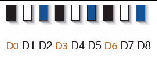
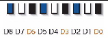
3. Populate DIMMs by location according to the following rules:
For example, populate D8/D5/D2 first; then D7/D4/D1 second; and finally, D6/D3/D0. See FIGURE 2-3.
Note that QR DIMMs are supported only in white sockets if adjacent blue socket contains a QR DIMM.
4. For maximum performance, apply the following rules:
|
DIMM speed rules are as follows:
|
|
|
The system operates all memory only as fast as the slowest DIMM configuration. |
DIMMs come in a variety of ranks: single, dual, or quad. Each DIMM is shipped with a label identifying its rank classification. TABLE 2-4 identifies the corresponding rank classification label shipped with each DIMM.
|
1. Attach an antistatic wrist strap.
2. Prepare the server to install options.
See Preparing the Server to Install Options.
3. Unpack the DIMMs and place them on an antistatic mat.
4. Determine the rank classification of the DIMMs to be installed.
See DIMM Rank Classification Labels.
5. To determine the slots into which to install the DIMMs, review the DIMM population rules to ensure that you are installing the DIMMs in a location that is consistent with the rules.
If you violate DIMM population rules, the performance of the server might be adversely affected.
6. To install a DIMM, do the following:
a. Remove the DIMM filler panel.
See Filler Panel Removal and Installation.
b. Ensure that the DIMM connector ejector levers are in the open position.
c. Align the DIMM with the connector (FIGURE 2-4).
Align the notch in the DIMM with the key in the connector. The notch ensures that the DIMM is oriented correctly.

d. Push the DIMM into the connector slot until both ejector levers close, locking the DIMM in place.
If the DIMM does not easily seat into the connector, verify that the notch in the DIMM is aligned with the key in the connector as shown in FIGURE 2-4. If the notch is not aligned, damage to the DIMM might occur.
e. Repeat Step a through Step d until all DIMMs are installed.
See Installing the Server Top Cover.
The server is shipped with at least one preinstalled CPU. The server can support a maximum of two CPUs. If you ordered a second CPU as an option for the server, the kit contains a CPU chip and a heatsink with thermal grease pre-applied.
|

|
Caution - CPU options should be installed only by a Sun qualified service technician. |
1. Attach an antistatic wrist strap.
2. Prepare the server to install options.
See Preparing the Server to Install Options.
The kit includes a CPU chip and a heatsink with the thermal grease pre-applied.
4. Install the CPU (FIGURE 2-5).
a. Properly orient the CPU with the socket alignment tabs and carefully place the CPU into the socket [1].
Ensure that the orientation is correct as damage might result if the CPU pins are not aligned correctly.

Ensure that the pressure frame sits flat around the periphery of the CPU.
c. Engage the release lever by rotating it downward and slipping it under the catch [2].
d. Orient the heatsink so that the two screws line up with the mounting studs [3].
e. Carefully position the heatsink on the CPU, aligning it with the mounting posts to reduce movement after it makes initial contact with the layer of thermal grease [3].
|
|
Caution - If the heatsink assembly is moved too much during its installation, the layer of thermal grease may not be distributed evenly, leading to component damage. |
f. Tighten the screws alternately one-half turn until fully seated.
See Installing the Server Top Cover.
The following topics are covered in this section:
FIGURE 2-6 show the physical drive locations for a Sun Fire X4170 Server with eight 2.5-inch hard drives.
FIGURE 2-6 Sun Fire X4170 Server Front Panel

FIGURE 2-7 shows the physical drive locations for the Sun Fire X4270 Server with 16 2.5-inch hard drives.
FIGURE 2-7 X4270 Server Front Panel

FIGURE 2-8 shows the physical drive locations for the Sun Fire X4275 Server with 12 3.5-inch hard drives.
FIGURE 2-8 Sun Fire X4275 Server Front Panel

TABLE 2-5 defines the number of hard disk drives (HDDs) supported by a given server type and configuration.
To install a hard disk drive, see the following procedure.
|
1. Attach an antistatic wrist strap.
2. Prepare the server to install options.
See Preparing the Server to Install Options.
| Note - You do not need to remove the server’s cover to install a hard drive. |
3. Unpack the hard disk drive and place it on an antistatic mat.
a. Refer to TABLE 2-5 and verify that your server will support the hard disk drive you intend to install.
b. Determine the drive slot location for the hard disk drive.
Select the first available hard disk drive location starting with the lowest numbered slot, HDD0. For example, if the server has two existing hard drives, install the hard drive in slot HDD2.
c. Remove the hard disk drive filler panel from the server chassis for the location into which you intend to install the hard drive.
See Filler Panel Removal and Installation.
d. Hard disk drives are physically addressed according to the slot in which they are installed. See FIGURE 2-6, FIGURE 2-7 and FIGURE 2-8 for hard drive locations.
e. Slide the drive into the drive slot until it is fully seated (see FIGURE 2-9).
FIGURE 2-9 Installing a Hard Disk Drive
f. Close the latch to lock the drive in place.
g. Repeat Step a through Step g until all hard drives are installed.
The following topics are covered in this section:
The server supports three or six PCIe cards depending on the server model.
You install the PCIe cards on the servers vertical PCIe risers, which are adjacent to the PCI slots. For the location of the PCI slots, see FIGURE 1-5 and FIGURE 1-6.
In addition to the PCIe card, the installation kit includes applicable host bus adapter installation information that you should reference for additional installation instructions.
|
|
|
Caution - This procedure requires that you handle components that are sensitive to static discharge. This sensitivity can cause the component to fail. To avoid damage, ensure that you follow antistatic practices as described in Performing Electrostatic Discharge and Antistatic Prevention Measures. |
|
|
Caution - Ensure that all power is removed from the server before removing or installing expansion cards. You must disconnect the power cables before performing this procedure. |
1. Attach an antistatic wrist strap.
2. Prepare the server to install options.
See Preparing the Server to Install Options.
3. Unpack the PCIe card and place it on an antistatic mat.
4. Determine the PCI slot into which you intend to install the PCIe card.
5. Remove the server back panel crossbar (see FIGURE 2-10 and FIGURE 2-11).
a. Loosen the captive Phillips screw on each end of the back panel crossbar.
b. Move the crossbar to the rear of the chassis and lift it up to remove it from the chassis.
FIGURE 2-10 Removing the Back Panel Crossbar From Sun Fire X4170 Server

FIGURE 2-11 Removing the Back Panel Crossbar From Sun Fire X4270 and X4275 Servers

c. Remove the PCI slot filler panel from the slot in the crossbar into which you intend to install the PCIe card.
FIGURE 2-12 shows the location of the PCI slot filler panels on the Sun Fire X4170 Server. The PCI slot filler panels are located in the same area on the Sun Fire X4270 and X4275 Servers.
FIGURE 2-12 Location of PCI Slots on the Sun Fire X4170 Server

6. Remove the PCIe riser from the server (see FIGURE 2-13).
a. Using a No. 2 Phillips screwdriver, loosen the captive screw on the end of the riser.
b. Lift up the riser and any PCIe cards attached to it as a unit.
Each server has three PCIe risers. On the Sun Fire X4170 Server, each PCIe riser can house only one PCIe card. On the Sun Fire X4270 and X4275 Servers, each PCIe riser can house two PCIe cards.
FIGURE 2-13 shows a Sun Fire X4170 Server PCIe riser.
FIGURE 2-13 Removing a PCIe Riser

7. Install the PCIe card into the PCIe riser (seeFIGURE 2-14 [1]).
Each server has three PCIe risers. On the Sun Fire X4170 Server, each PCIe riser can house only one PCIe card. On the Sun Fire X4270 and X4275 Servers, each PCIe riser can house two PCIe cards.
FIGURE 2-14 Installing a PCIe Card

8. Install the PCIe riser with installed PCIe card into the PCI slot (see FIGURE 2-14 [2]).
a. Lower the PCIe riser and the installed cards into the server.
b. Tighten the captive No. 2 Phillips screw securing the riser to the motherboard.
c. Install the back panel crossbar.
Slide the crossbar down over the PCIe risers. The crossbar is secured with two captive Phillips screws.
9. If you are installing a SAS RAID host bus adapter (HBA) PCIe card, install and connect the cables that connect the PCIe card to the hard disk drive cage; otherwise skip to the next step.
See FIGURE 2-15 for Sun Fire X4170 Server, FIGURE 2-16 for Sun Fire X4270 Server, and FIGURE 2-17 for the Sun Fire X4275 Server.
FIGURE 2-15 Installing the SAS PCIe/Hard Disk Drive Cage Cable Into the Sun Fire X4170 Server

FIGURE 2-16 Installing the SAS PCIe/Hard Disk Drive Cage Cable in the Sun Fire X4270 Server

FIGURE 2-17 Installing the SAS PCIe/Hard Disk Drive Cage Cable in the Sun Fire X4275 Server

10. For additional PCIe card installation requirements, refer to the installation information in the PCIe card shipping kit.
11. Install the server top cover.
See Installing the Server Top Cover.
If the server has only one power supply, you can install a second power supply for redundancy.
|
1. Attach an antistatic wrist strap.
2. Prepare the server to install options.
See Preparing the Server to Install Options.
| Note - You do not need to remove the server’s cover to install a power supply. |
3. Unpack the power supply and place it on an antistatic mat.
a. Remove the filler panel from the server’s power supply bay.
See Filler Panel Removal and Installation.
b. Align the power supply with the empty power supply chassis bay.
c. Slide the power supply into the bay until it is fully seated (see FIGURE 2-18 and FIGURE 2-19).
FIGURE 2-18 Installing a Power Supply Into a Sun Fire X4170 Server

FIGURE 2-19 Installing a Power Supply Into a Sun Fire X4270 or X4275 Server

After you have installed the optional components, you must reinstall the top cover onto the server.
|
1. Place the top cover on the chassis.
Set the cover down so that it hangs over the rear of the server by about 1 inch (25.4 mm) (see FIGURE 2-20 [1] or FIGURE 2-21 [1]).
2. Slide the top cover forward until it cover side latches engage [1 and 2].
3. To close the fan cover, press down on the fan cover with both hands [3].
FIGURE 2-20 Installing the Top Cover on the Sun Fire X4170 and X4270 Servers

FIGURE 2-21 Installing the Top Cover on the Sun Fire X4275 Server

| Sun Fire X4170, X4270, and X4275 Servers Installation Guide | 820-5827-13 |
Copyright © 2009 Sun Microsystems, Inc. All rights reserved.
 Prepare Server to Install Options