| C H A P T E R 5 |
|
SAN Configurations |
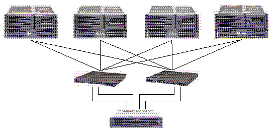
This chapter presents several SAN configurations you can use.
|
Note - Do not use a Sun StorEdge 3511 SATA array to store single instances of data. It is more suitable for use in configurations where the array has a backup or archival role. |
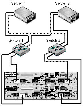
FIGURE 5-2 shows a Sun StorEdge 3510 FC array in a full-duplex SAN configuration. FIGURE 5-3 shows a Sun StorEdge 3511 SATA array in a full-duplex SAN configuration.
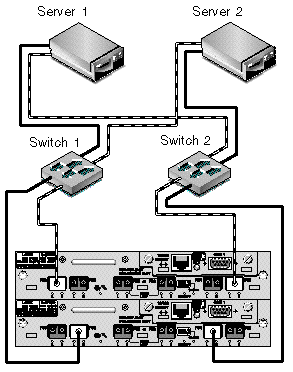
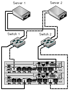
The general procedure for creating this configuration follows.
1. Check the position of installed SFP modules. Move them as necessary to support the connections needed.
2. Connect expansion units if needed.
For information about connecting multiple expansion units, see Sun StorEdge 3510 FC Array High-Capacity Configurations or Sun StorEdge 3511 SATA Array High-Capacity Configurations.
For information about connecting Sun StorEdge 3511 SATA expansion units to Sun StorEdge 3510 FC arrays, see Combining Sun StorEdge 3510 FC Arrays and Sun StorEdge 3511 SATA Expansion Units.
3. Configure cache optimization.
4. Ensure that the fibre connection is set to point-to-point.
5. Ensure only one target ID per channel is configured.
6. Create at least two logical drives and configure spare disks.
7. Create one or more logical drive partitions for each server.
8. Map Logical Drive 0 to channels 0 and 4 of the primary controller
9. Map Logical Drive 1 to channels 1 and 5 of the secondary controller.
10. If more than two logical drives were created, map even-numbered logical drives to channels 0 and 4 of the primary controller and odd-numbered logical drives to channels 1 and 5 of the secondary controller.
11. Connect the first switch to port FC 0 of the upper controller and port FC 1 of the lower controller.
12. Connect the second switch to port FC4 of the lower controller and port FC5 of the upper controller.
13. Connect each server to each switch.
14. Install and enable multipathing software on each connected server.
15. After completing the configuration, save the configuration using the "Save nvram to disks" menu option in the firmware application or the "save configuration" option in Sun StorEdge Configuration Service.
|
Note - Do not use a Sun StorEdge 3511 SATA array to store single instances of data. It is more suitable for use in configurations where the array has a backup or archival role. |
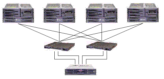
FIGURE 5-5 shows a Sun StorEdge 3510 FC array in a redundant point-to-point SAN configuration. FIGURE 5-6 shows a Sun StorEdge 3511 SATA array in a redundant point-to-point SAN configuration.
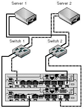
The general procedure for creating this configuration follows.
1. Check the position of installed SFP modules. Move them as necessary to support the connections needed.
2. Connect expansion units if needed.
For information about connecting multiple expansion units, see Sun StorEdge 3510 FC Array High-Capacity Configurations or Sun StorEdge 3511 SATA Array High-Capacity Configurations.
3. Configure cache optimization.
4. Ensure that the fibre connection is set to point-to-point mode.
6. Create at least two logical drives and configure spare disks.
7. Assign even-numbered logical drives beginning with Logical Drive 0 to the primary controller.
8. Assign odd-numbered logical drives beginning with Logical Drive 1 to the secondary controller.
9. Create one or more logical drive partitions for each server.
10. Map the LUNs from even-numbered logical drives beginning with Logical Drive 0 to channels 0 and 4 of the primary controller.
11. Map the LUNs from even-numbered logical drives beginning with Logical Drive 1 to channels 1 and 5 of the secondary controller.
|
Note - See Fibre Channel Protocols for a description of the maximum number of devices you can map in various configurations. |
12. Connect the first switch to port FC 0 of the upper controller and port FC 1 of the lower controller.
13. Connect the second switch to port FC4 of the lower controller and port FC5 of the upper controller.
14. Connect each server to each switch.
15. Install and enable multipathing software on each connected server.
16. After completing the configuration, save the configuration using "Save nvram to disks" menu option in the firmware application and the "save configuration" option in Sun StorEdge Configuration Service.
Copyright © 2007, Dot Hill Systems Corporation. All rights reserved.