Configuring SAP R/3 for the SAP BAPI Adapter
For the SAP BAPI Adapter to interact successfully with SAP R/3, you must configure the SAP R/3 application as described in this section.
The SAP R/3 screen captures in this section correspond to SAP GUI version 6.2, and SAP R/3 version 4.7. They are included to illustrate the general nature of the procedures, and contain only example values. Refer to the documentation supplied with your SAP R/3 system to determine the exact procedures.
Creating the RFC Destination for the Adapter
For the SAP BAPI Adapter to receive communications from SAP R/3, you must set the Adapter up as an RFC destination in SAP R/3 as described below.
 To create the RFC destination for the Adapter
-
In the SAP R/3 window, click the forward arrow to display the navigation box if necessary.
-
Type SM59 into the text field and press ENTER.
Figure 1–1 Navigating to the SM59 Transaction

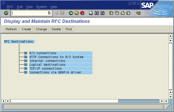
This displays the RFC Destination Maintenance window.
Figure 1–2 RFC Destination Maintenance Window
-
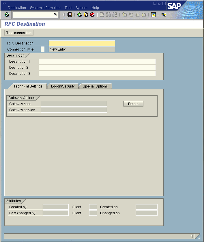
Click TCP/IP connections and Create to display the RFC Destination entry window.
Figure 1–3 RFC Destination Entry Window
-
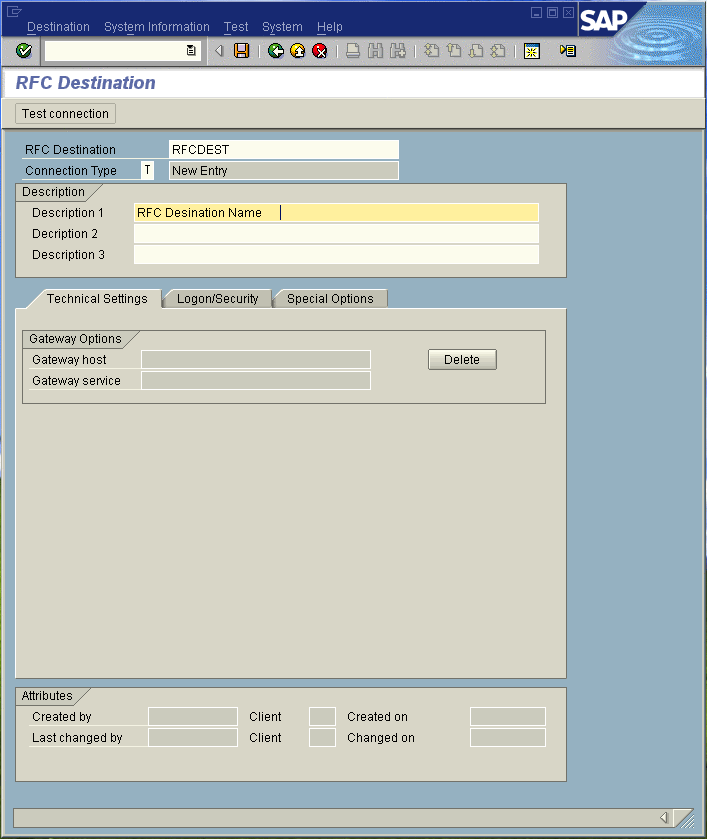
Type in the name of the RFC Destination (use a Logical System name refer to Name the Logical System), an accompanying Description, and enter <T> for the Connection Type (TCP/IP).
Figure 1–4 RFC Destination
-
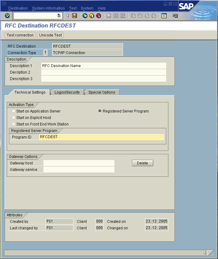
Click Save to display the RFC Destination window corresponding to your entry.
-
Select the Registered as Server Program option.
-
Enter the Program ID and click Save.
This program ID must be exactly the same as that specified in the Adapter Program ID property. This value is case sensitive. For more information, refer to the Inbound Server Connection Settings.
Figure 1–5 RFC Destination Window
-
Click Test Connection, which tests the connection for logon speed and message transfer speed. When the inbound Project is deployed and running, the results are displayed in a table; otherwise, return code 3 is displayed.
Figure 1–6 Connection Test Results

Configuration Needed in SAP R/3 to Send and Receive IDocs
For the SAP BAPI Adapter to interact successfully with the SAP R/3 system, you must configure the SAP R/3 system as described in this chapter.
The SAP R/3 screen captures in this chapter correspond to SAP GUI version 6.2, and SAP R/3 version 4.0. They are included to illustrate the general nature of the procedures, and contain only example values. Refer to the documentation supplied with your SAP R/3 system to determine the exact procedures.
Figure 1–7 Distribution Model Hierarchy
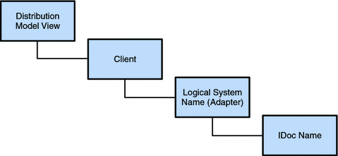
Following this high-level setup, you need to define Communications parameters in SAP R/3 to specify the correct routing of IDocs (either inbound to or outbound from SAP R/3). The hierarchy of this Communication system is shown in the following figure.
Figure 1–8 Communications Hierarchy
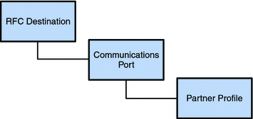
The RFC Destination defines the entity to which Remote Function Calls (RFCs) can be made; it is the same as the Logical System in the Distribution Model. The Communications Port defines a channel for communication of IDocs. The Partner Profile acts as an identifier for the eGate system, and provides a communications gateway by incorporating elements of the ALE interface.
Configuring the Distribution Model
You need to complete the following in SAP R/3 to run a RFC BAPI inbound.
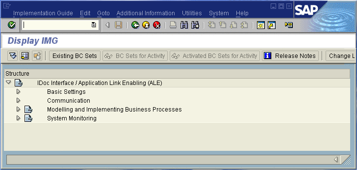
Figure 1–9 SAP R/3 System Window
 To Name the Logical System
Transaction: SALE
-
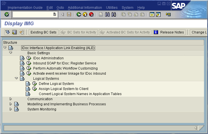
In the SAP R/3 System home window (shown above), type SALE into the command field and click Enter to display the Distribution (ALE) Structure window.
-
Expand the tree to display IDoc Interface / Application Link Enabling (ALE) > Basic Settings > Logical Systems > Define Logical System.
-
Click the Activity button to select Define Logical System. This displays the Logical Systems Overview window.
-
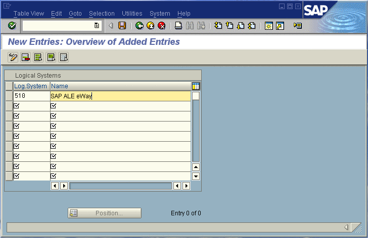
Click the New entries button to display the New Entries window.
-
Enter the logical name for your SAP Adapter using capital letters and a brief descriptive name.
-
Click Save. The Change Request Entry window appears.

-
Click the Create request button, to display the Create Request window.
-
Enter a short description (e.g., Adapter Test) and click Save. The Change Request entry window appears.
-
Click Enter to add the new data into the system. You are now returned to the Logical Systems Overview window, and the new Logical System appears in the list.
-
Click Save and select the Back button repeatedly until the SAP R/3 System window appears
 To Specify the Distribution Model
We recommend that you use the Z prefix when defining a name. This prefix is reserved for external use, and will not conflict with any SAP naming conventions. Using the Z prefix will also prevent any interference with standard SAP functionality or conflicts with standard SAP terminology.
Transaction: SALE
-
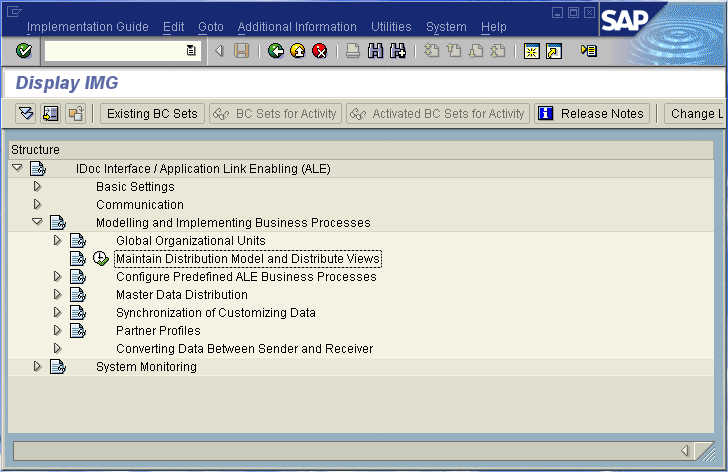
In the SAP R/3 System home window, type SALE into the command field and click Enter to display the Distribution (ALE) Structure window.
-
Click the Activity button next to Maintain Distribution Model and Distribute Views to display the Maintain Distribution Model window.

-
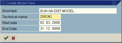
Select the Menu path Edit > Model View > Create to display the Create Model View dialog box.
-
Enter the logical name you want for the new Distribution Model View, along with a brief descriptive name or message (for your own use).
-
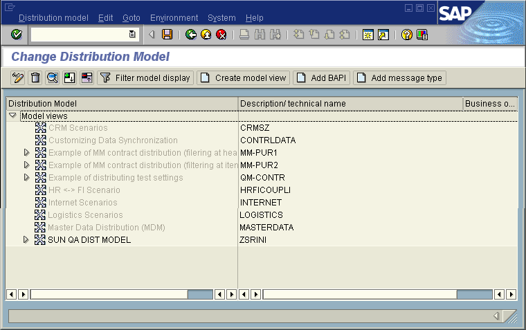
Click Continue (Enter), which returns you to the previous window. Your new Model View now appears in the tree, as shown in the following figure.
-
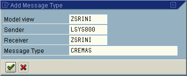
Highlight the new entry and select Add Message Type. This displays the Add Message Type dialog box.
-
Type the desired values for the four parameters into the text boxes, or select them from the drop-down menus. For example, CREMAS is the message type used for Creditor Master Data.
-
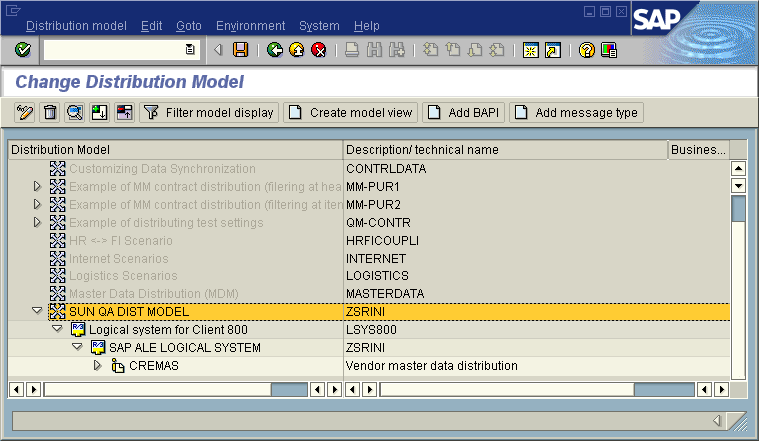
Select Continue (Enter), which returns you to the previous window. The values you select now appear in the Distribution Model tree, as shown in the following figure.
-
Save your entry, click Back and then Cancel to return to the Distribution Structure window.
Configuring Communications
This section describes the following communication configuration tasks.
Figure 1–10 SAP R/3 System Window

 To Define the Communications Port
Transaction: WE21
The Communications Port defines the type of connection with the Partner (see To Create a Partner Profile). This task is used to specify the outbound file name, directory path, and any associated function modules.
-
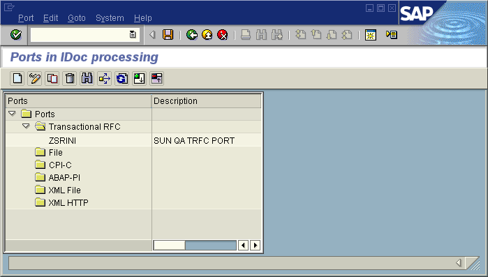
In the SAP R/3 System home window, type WE21 into the command field and click Continue (Enter) to display the WF-EDI Port Definition window.
-
Expand the tree under Transactional RFC to display the currently-defined Ports.
-
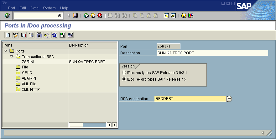
Select the desired Port from the list, or select Change to display the Port Definition for Asynchronous RFC Overview window.
-
Type in a Version (specifies IDoc record type), Logical destination, and Description, matching the entries made previously.
-
Select Enter, which displays the Change Request Query dialog window. [Note that you must have CTS (Correction and Transport System) turned on for this screen to be displayed.]
-
Select Create Request, which displays the Create Request dialog window.
-
Enter a Short description and Save.
-
Select Back repeatedly to return to the SAP R/3 System window.
 To Create a Partner Profile
Transaction: WE20
This task is used to demonstrate how to create the Partner for the Logical System you created earlier. Note that the LS Partner Type is used for all ALE distribution scenarios.
-
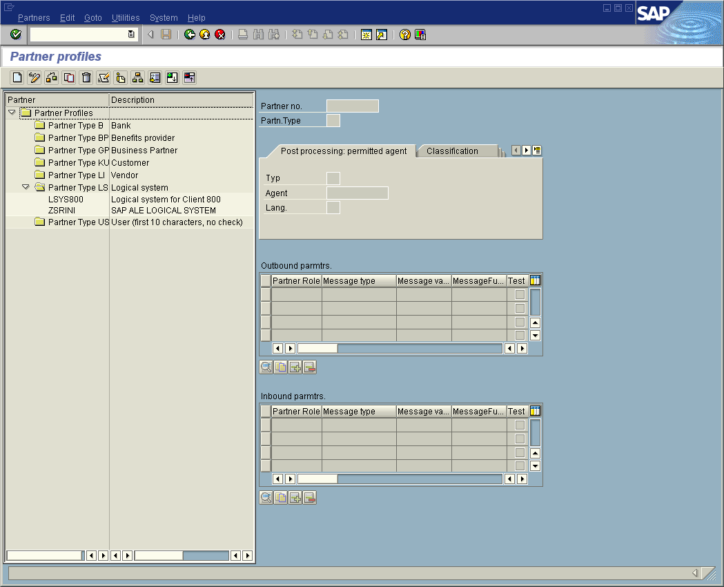
In the SAP R/3 System home window, type WE20 into the command field and then click Continue (Enter) to display the Partner Profile: Initial Screen window.
-
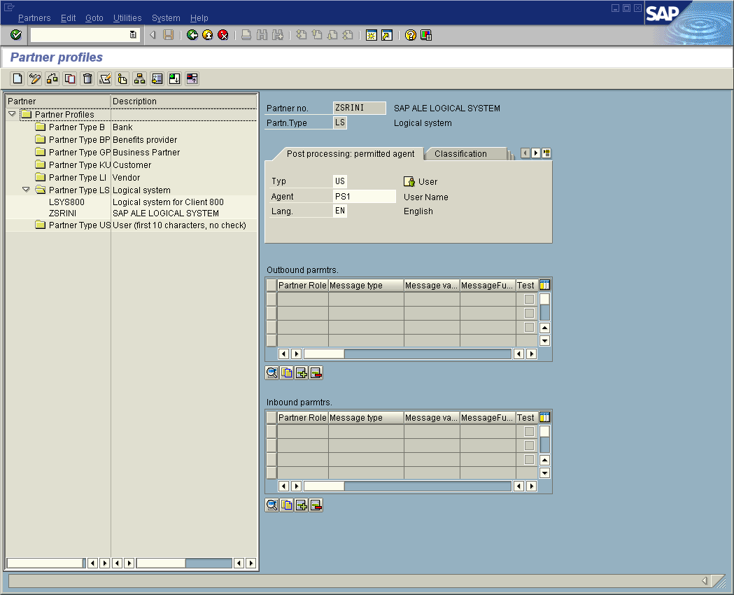
Type the name of the logical system created previously into the Partner number field, select LS for the Partner type, and select Create. This creates the Partner, and displays the Create Partner Profile <Partner Number> window.
-
Under the Classification tab, select ALE for the Partner class and A (Active) for the Partner status, then Save. You now have created the Partner, and need to continue to the next section to configure the Partner Profile.
 To Configure a Partner Profile
Transaction: WE20
This task is used to demonstrate how you configure the Inbound/Outbound Parameters in the Partner Profile.
-
In the Partner Profile: Initial Screen window, select the desired Partner Number, for example ZSRINI.
-
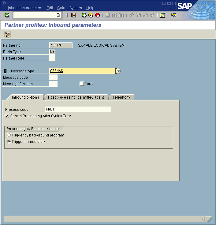
Select the Inbound parameters
-
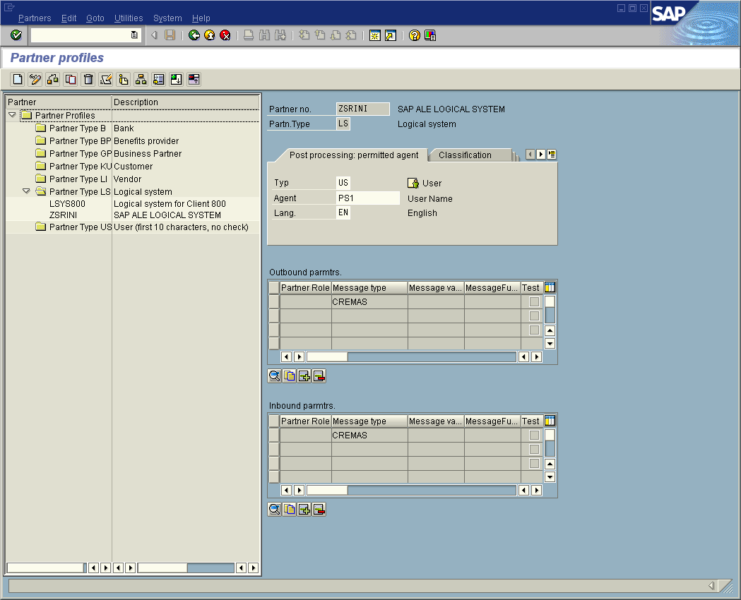
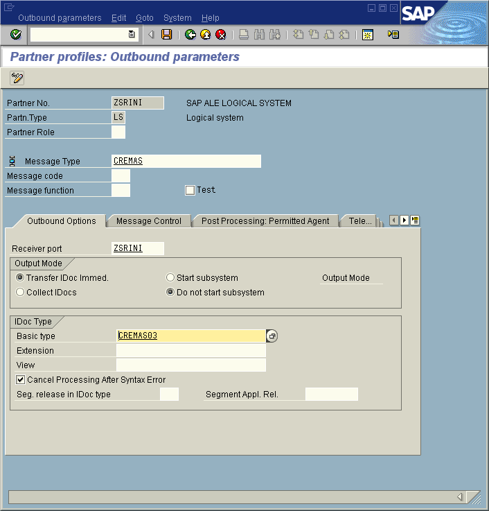
Select CREMAS as a Message type and CRE1 as a Process code from the drop-down menus, then click Save. The entries now appear in the list in the EDI Partner Profile: Inbound Parameters Overview window.
-
Follow the same procedure for Outbound parameters, as seen in the following figure.
-
After making your entries, Save and then clickBack to get to the main SAP R/3 System window.
- © 2010, Oracle Corporation and/or its affiliates
