Creating the bpBatch_Inbound_LocalFileIn_FTPOutProject
These following topics provide step-by-step instructions for manually creating the bpBatch_Inbound_LocalFileIn_FTPOut Project.
This topic describes how manually create the Batch_FTPIn_LFOut_Sample Project.
 To Create a Project
The first step is to create a new Project in the NetBeans IDE
-
Start the NetBeans IDE
-
Click the New Project icon, or select File ⇒ New Project to initiate the New Project wizard.
-
In Step 1 of the Wizard, select CAPS ⇒ ESB from the Categories column and CAPS Repository-Based Projectfrom the Projects column, and click Next.
-
In Step 2 of the Wizard, change Project Name to prjBatch_Inbound_LocalFileIn_FTPOutProject, and click Finish.
Creating the bpBatch_Inbound_LocalFileIn_FTPOut Business Process
 To Create the Business Process
The first step in the sample process is to add a Business Process (BP) to the Project.
-
From the Project Explorer panel, right-click brjBatch_Inbound_LocalFileIn_FTPOut.
-
Select New⇒Business Process from the context menu.
-
Rename the Business Process to bpBatch_Inbound_LocalFileIn_FTPOut, and click Save.
-
In the Project Explorer tree, expand the CAPS Components Library, expand Adapters, and then expand Batch eWay.
-
Expand the BatchInbound, and BatchLocalFileBatchFTP nodes to expose the Business Process elements.
-
Populate the design canvas with the following elements from the Project Explorer.
-
Under BatchInbound, add receive
-
Under BatchLocalFile, add read
-
Under BatchFTP, addput
-
-
To link the modeling elements, click the element’s connector and drag it to the next element’s connector, as follows:
-
Start⇒BatchInbound.receive
-
BatchInbound.receive⇒BatchLocalFile.read
-
BatchLocalFile.read⇒BatchFTP.put
-
BatchFTP.put⇒End

-
Adding Business Rules to the Design Elements
Business Rules define the relationship between the input and output Attributes of the elements.
 To Add Business Rules
-
Right-click the link between BatchInbound.receive and BatchLocalFile.read Activities and select Add Business Rule from the context menu.

-
From the Business Process Designer toolbar, click the Display Business Rules Designer icon.
The Business Rule Designer opens in the lower half of the Business Process Designer window.
-
Click the Business Rule icon between the BatchInbound.receive and BatchLocalFile.read Activities.
The Business Rule Attributes appear in the Business Rule Designer.
-
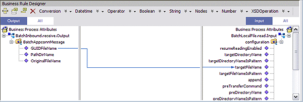
To create the BatchInbound.receive⇒BatchLocalFile.read Business Rule, in the Business Rules Designer, click GUIDFileName and drag it to targetFileName.
A link appears between the two nodes.

-
Right-click the link between the BatchLocalFile.read and BatchFTP.put Activities, and select Add Business Rule from the context menu.
-
Double-click the new Business Rule.
-
From the Business Rule Designer, under BatchLocalFile.read.Output, map payload in the Output pane to payload under BatchFTP.put.Input in the Input pane.

-
From the Business Process Designer toolbar, click the Synchronize Graphical Model and Business Process Code icon.
This synchronizes the graphical interface to the Business Process code.
-
Click Save All.
 To Create a Connectivity Map
The Connectivity Map provides a canvas for assembling and configuring a Project’s components.
-
In the Project Explorer, right-click the prjBatch_Inbound_LocalFileIn_FTPOut Project and select New⇒Connectivity Map from the context menu.
The New Connectivity Map appears and a node for the Connectivity Map is added to the Project Explorer tree labeled CMap1.
-
Rename the CMap1 Connectivity Map to cmBatch_Inbound_LocalFileIn_FTPOut.
 To Generate the Connectivity Map
Once your BPEL process is completed you can use it to generate your Connectivity Map.
-
Drag and drop the bpBatch_Inbound_LocalFileIn_FTPOut bpel process from the Project window to the Connectivity Map canvas.
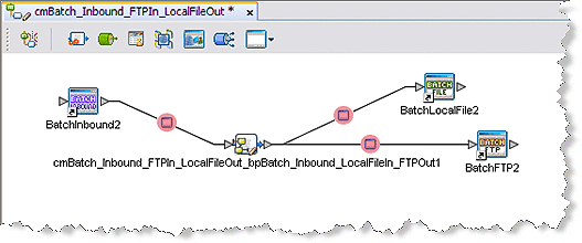
The cmBatch_Inbound_FTPIn_LocalFileOut_bpBatch_Inbound_LocalFileIn_FTPOut1 service is added to the canvas.
-
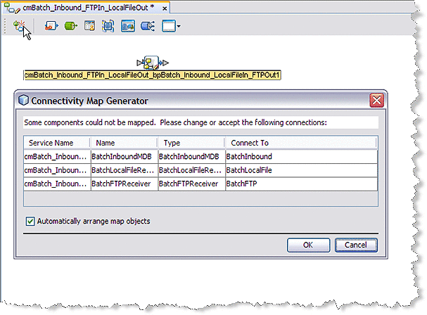
Click the Connectivity Map Generator icon. The Connectivity Map Generator dialog box appears listing the necessary components and bindings to generate the Connectivity Map. Click OK.

The External applications are added to the Connectivity Map and the Bindings are created. The red squares in the bindings represent the Batch Adapters. The red color indicates that the adapter properties have not been configured.

-
Save your current work.
Creating an Environment
Environments include the External Systems, Logical Hosts, Application Servers, and Message Servers used by the Project and contain the configuration information for these components.
 To Create an Environment
-
Click the Services tab.
-
In the Services tree, right-click CAPS Environments, and click New Environment.
A new Environment is added to the Services tree.
-
Rename the new Environment to envBatch_Inbound_LocalFileIn_FTPOut.
-
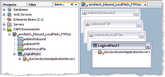
Right-click envBatch_Inbound_LocalFileIn_FTPOut and select New ⇒ BatchInbound External System.
-
Name the External System esBatchInbound and click OK.
The esBatchInbound box is added to the Environment Editor.
-
Right-click envBatch_Inbound_FTPIn_LocalFileOut and select New ⇒ BatchFTP External System.
-
Name the External System esBatchFTP and click OK.
The esBatchFTP box is added to the Environment Editor.
-
Right-click envBatch_Inbound_FTPIn_LocalFileOut and select New ⇒ BatchLocalFile External System.
-
Name the External System esBatchLocalFile and click OK.
The esBatchLocalFile box is added to the Environment Editor.
-
Right-click envBatch_Inbound_FTPIn_LocalFileOut and select New ⇒ Logical Host.
The LogicalHost icon is added to the Environment and LogicalHost1 is added to the tree.
-
Right-click LogicalHost1 and select New ⇒ Sun Java System Application Server.
A new Application Service is added to the tree under LogicalHost1.

-
Save the Project.
Configuring the Adapters' Properties
The prjBatch_Inbound_LocalFileIn_FTPOut sample project contains three Adapters, each represented in the Connectivity Map as a node between an External Application and a Collaboration. The Adapters facilitate communication and movement of data between the external applications and the Sun Enterprise Service Bus.
The Adapter properties must be set from both the Project Explorer’s Connectivity Map and the Services tree.
 To Configure the BatchInbound Adapter Properties
-
From the Connectivity Map, double-click the BatchInbound Adapter.
The Adapter Properties Editor appears.
-
Modify the properties for your system, including the settings for the BatchInbound Adapter in the following table, and click OK.
BatchInbound Adapter Connectivity Map Properties
Settings - Set as directed, otherwise use the default settings
Directory Name
Your input directory (full address)
File Name
BatchInbound.txt
The BatchInbound Adapter Environment properties can keep the default settings for this sample.
 To Configure the BatchLocalFile Adapter Properties
-
From the Connectivity Map, double-click the BatchLocalFile Adapter.
The Adapter Properties Editor appears.
-
Modify the properties for your system, including the settings in the following table, and click OK.
BatchLocalFile Adapter Properties
Target Location - Set as directed, otherwise use the default settings
Append
Yes
Target File Name
BatchLocalFileOut.txt
Target File Name is Pattern
No
Target Directory Name
The directory on the system where files are sent.
Target Directory Name is Pattern
No
-
To refresh and save your default BatchLocalFile Adapter properties, double-click the BatchLocalFile External System in the Services tree to open the Properties Editor.
-
Click OK to save the default settings.
Configuring the BatchFTP Adapter Properties
 To Modify the BatchFTP Adapter Connectivity Map Properties
-
From the Connectivity Map, double-click the BatchFTP Adapter.
The Adapter Properties Editor appears.
-
Modify the BatchFTP Adapter Connectivity Map properties for your system, including the settings in the following table, and click OK.
BatchLocalFile Adapter Properties
Target location - Set as directed, otherwise use the default settings
Target Directory Name
The directory on the external system (absolute path) from which files are retrieved or sent
Target File Name
The FTP remote file name which is retrieved or sent
 To Modify the BatchFTP Adapter Properties
-
From the Services tree, right-click the BatchFTP External System (esBatchFTP in this sample), and select Properties.
The Properties Editor opens to the BatchFTP Adapter Environment properties.
-
Modify the BatchFTP Adapter Environment properties for your system, including the settings in the following table, and click OK.
BatchFTP Adapter Environment-Configuration Parameters
Target location - Set as directed, otherwise use the default settings
FTP
Set as directed, otherwise use the default settings.
Host Name
The name of the external system to which the Adapter connects
Password
Password required to log into the
external system
Server Port
Port number to use to connect to the FTP server
User Name
User ID used to login to the external system
Creating the Deployment Profile
A Deployment Profile is used to assign Collaborations and message destinations to the Sun Java System Application Server and message server.
 To Create the Deployment Profile
-
Select the Projects tab, right-click the Project (prjBatch_Inbound_LocalFileIn_FTPOut) and select New⇒Deployment Profile.
-
Enter a name for the Deployment Profile.
For this Project, use dpBatch_Inbound_LocalFileIn_FTPOut . Make sure that the selected Environment is envBatch_Inbound_LocalFileIn_FTPOut.
-
Click OK.
-
The Project’s components are automatically mapped to their respective system windows.
Note –If any of your Project components did not successfully map to an external system, open each of your Adapter’s configuration properties (Connectivity Map and Environment) and click OK to close and save the current configuration, then click Automap again.
-
Save the Project.
Creating and Starting the Domain
A domain is an instance of a Logical Host. After the domain is created, the Project is built and then deployed.
 To Create and Start the Domain
-
Navigate to your JavaCAPS6\logicalhost directory, where JavaCAPS6 is the location of your Sun Java Composite Application Platform Suite installation.
-
Double-click the domainmgr.bat file.
The Domain Manager appears.
-
Do one of the following:
-
If you have already created a domain, select your domain in the Domain Manager and click Start an Existing Domain.
-
If there are no existing domains, click Yes.
The Create Domain dialog box appears.
-
Make any necessary changes to the Create Domain dialog box and click Create.
-
Select the domain and click the Start an Existing Domain button
The new domain is added to the Domain Manager.
-
-
Once your domain is started, a green check mark indicates that the domain is running.
-
Building and Deploying the Project
The Build process compiles and validates the Project’s Java files and creates the Project EAR file.
 To Build the Project
-
From the Deployment Editor toolbar, click the Build icon.
If there are any validation errors, a Validation Errors pane will appear at the bottom of the Deployment Editor and displays information regarding the errors.
-
Make any necessary corrections and click Build again.
 To Deploy the Project
-
From the Deployment Editor toolbar, click the Deploy icon.
The Deploy prompt appears.
-
Click Yes.
A message appears when the project is successfully deployed.
 To Run the Sample
- © 2010, Oracle Corporation and/or its affiliates
