Chapter 2 Developing Your Implementation Specifications
The deployment architecture is a high-level technical description of your Java ES solution, and it does not have all of the information needed to install and configure the solution. This chapter describes the process of analyzing a deployment architecture and developing a set of implementation specifications. The reason you develop implementation specifications is to help you prepare the additional information you will need when you install and configure your solution.
This chapter describes the implementation specifications in the following sections:
Analyzing the Deployment Architecture
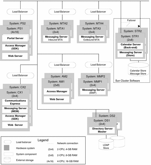
A typical deployment architecture is illustrated in Figure 2–1. This deployment architecture defines a Java ES solution that provides portal and communications services. This particular architecture uses Access Manager to provide single sign-on to the communications services, and it uses both Portal Server and Communications Express to deliver the messaging and calendar services to end users. This architecture includes components from the Communications Suite.
Figure 2–1 Example Deployment Architecture

Figure 2–1 contains much information about the solution, including the following:
-
The number of computers used in the solution
-
The number of CPUs and the amount of RAM required for each computer
-
The component instances installed on each computer
-
The number of instances of each component used in the solution
-
The redundancy strategies used in the solution (load balancing, Directory Server multimaster replication, and Sun Cluster technology) to meet quality-of-service requirements
-
The distributed installation of the Messaging Server subcomponents, another technique used to meet quality-of-service requirements
These characteristics of the example deployment architecture affect how the solution is installed and configured. You begin planning for your installation by analyzing your deployment architecture in the same way, observing how many computer systems are used, how many component instances are installed on each computer system, which redundancy strategies are used, and so on.
Developing Your Computer Hardware and Operating System Specification
In addition to the information that appears in the deployment architecture, you must specify the operating system that will be used on each computer used in your solution. You must also develop more information about the hardware on which you will install. Your decisions will be based on your quality of service requirements, and represent your best guess at the hardware and operating systems required to satisfy your quality of service requirements.
To meet the quality of service requirements for the deployment architecture shown in Figure 2–1the operating system and computer hardware specifications in Table 2–1 were developed.
Table 2–1 Computer Hardware/OS Specification for the Sample Deployment Architecture|
Computer System |
Hardware Model |
Number of CPUs |
RAM (in Gigabytes) |
Number of Disks |
Operating System |
|---|---|---|---|---|---|
|
mscs01 mscs02 |
Sun Fire V440 Server |
4 |
16 |
4 |
Solaris 9 |
|
commx01 commx02 |
Sun Fire V240 Server |
2 |
4 |
2 4 |
Solaris 10 |
|
ds01 ds02 |
Sun Fire V240 Server |
2 |
8 |
4 |
Solaris 10 |
|
am01 am02 |
Sun Fire V240 Server |
2 |
8 |
4 |
Solaris 10 |
|
ms-mmp01 ms-mmp02 |
Sun Fire V240 Server |
2 |
4 |
2 |
Solaris 10 |
|
ms-mtai01 ms-mtai02 |
Sun Fire V240 Server |
2 |
4 |
2 |
Solaris 10 |
|
ms-mtao01 ms-mtao02 |
Sun Fire V240 Server |
2 |
4 |
2 |
Solaris 10 |
|
ps01 ps02 |
Sun Fire V440 Server |
4 |
16 |
4 |
Solaris 10 |
|
protect |
Sun Fire V240 |
2 |
4 |
2 |
Solaris 10 |
You must develop similar information about the computer systems used in your solution.
Tip –
Once the Computer Hardware/OS specification is complete, the computer systems can be set up. Memory and disk drives can be installed, operating system can be installed, and the systems made ready for installation of Java ES components.
Developing a Network Connectivity Specification
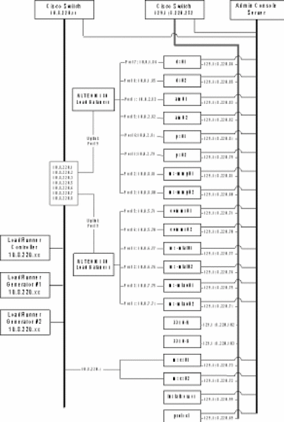
The deployment architecture contains much of the information needed to connect all of the hardware used in a solution. To help you develop the additional information you need to connect your network, you need to prepare a network connectivity specification like the example in Figure 2–2.
Figure 2–2 Example Network Connectivity Specification

The network connectivity specification for the example deployment architecture adds the following information that is not found in the deployment architecture diagram:
-
IP addresses for every computer and hardware load balancer used in the solution
-
Load balancer port numbers that are used to connect the computers to the load balancers
-
The IP addresses for the load balancers show the logical addresses that are used to access the services provided by load-balanced computers
You must develop similar information about the connectivity required for your solution.
Tip –
When the network connectivity specification is complete, the network can be connected and made ready for the installation and configuration of your Java ES components.
Developing Your User Management Specifications
The process of installing and configuring your Java ES solution configures your LDAP directory. Installing and configuring Java ES creates both an LDAP schema and an LDAP directory tree. The details of the schema and the directory tree are determined by values that you input during the installation and configuration process. Therefore, installation planning includes developing specifications for a schema and a directory tree structure that will support your Java ES solution.
Your directory tree structure and your schema must support the services your solution provides. This section provides basic descriptions of the options that are available, and the services that each option supports. The main purpose of this section, however, is describing how you select input values for the Java ES installer and the Java ES configuration tools in order to create a schema and a directory tree structure that will support your Java ES solution.
For more information on choosing a schema and designing a directory tree, see additional documentation, such as Sun Java System Directory Server Enterprise Edition 6.0 Deployment Planning Guide.
Specifying the LDAP Schema for a Solution
Java ES solutions that use Directory Server can use either of two versions of a standard LDAP schema, which are known as Schema 1 and Schema 2. Your user management specification must specify whether your solution uses Schema 1 or Schema 2.
Schema 2 supports the use of Access Manager, and Access Manager's single sign-on feature. If a solution uses Access Manager, it must use Schema 2.
The installation process configures the directory for the specified schema as follows:
-
To establish a Schema 1 directory, simply install Directory Server. Schema 1 is the default schema version.
-
To establish a Schema 2 directory, install Directory Server and Access Manager. Installing Access Manager modifies the directory and converts it to a Schema 2 directory.
Tip –If Directory Server and Access Manager are installed on one computer in one installer session, the directory is configured for Schema 2.
If your solution is distributed, you install Directory Server first, on one computer. You then install Access Manager on a second computer. When you install Access Manager you specify the existing directory on the remote computer, and the directory's schema is configured for Schema 2.
Depending on your solution, the following procedures for extending the schema might be necessary:
-
If your solution uses components from the Communications Suite (Messaging Server and or Calendar Server), your installation process must apply some additional schema extensions with the Directory Preparation Tool. These extensions are applied before Messaging Server or Calendar Server are installed. They can be applied to either Schema 1 or Schema 2 directories. For an example of an installation plan that includes instructions for the Directory Preparation Tool, see Sun Java Enterprise System 2005Q4 Deployment Example: Telecommunications Provider Scenario
-
If your solution uses Schema 2, the installation process must apply some additional schema extensions with Delegated Administrator to support Access Manager authentication and authorization for the messaging and calendar services. For an example of an installation plan that applies these schema extensions, see Sun Java Enterprise System 2005Q4 Deployment Example: Telecommunications Provider Scenario.
Your LDAP schema specification identifies the schema used in your solution and any schema extensions required by your solution.
Specifying the Directory Tree Structure for a Solution
The LDAP directory for a Java ES solution can be simple or complex, depending on the solution's needs for organizing user data. LDAP directories are, by their nature, flexible in structure. Java ES does not impose structure on the directory, but the installation and configuration process does implement a directory tree structure. You must design your directory tree before you begin the installation and configuration process.
The installation and configuration process establishes the directory tree structure as follows:
-
Running the installer to install Directory Server requires an input value for the directory's base suffix (also referred to as root suffix or root DN). The Java ES installer uses the input value to establish the directory's base suffix. You must specify the base suffix name for your directory tree.
Tip –Solutions with simple directory trees, that do not use Messaging Server or Calendar Server, can store user and group data directly under the base suffix.
-
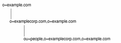
Running the Messaging Server (a Communications Suite component) configuration wizard to create a Messaging Server instance requires an input value for an LDAP organization DN. The configuration wizard branches the directory tree and creates an LDAP organization using the DN input in the wizard. This organization represents the email domain managed by the Messaging Server instance. The wizard also configures the Messaging Server instance to use the email domain organization for user and group data. The installation plan includes the DN for the email domain organization. For an example of a directory tree structure created by this process, see Figure 2–3. In the example, the base suffix created by the installer is o=examplecorp. The email domain organization created by the Messaging Server configuration wizard is o=examplecorp.com,o=examplecorp.
-
The configuration wizards for Calendar Server, Communications Express, Instant Messaging, and Delegated Administrator (Communications Suite components) require an input value for an LDAP DN. (The names that appear in the wizards vary.) If a solution uses single sign-on, the same value is input in all of the configuration wizards. The input value is the email domain organization created by the Messaging Server wizard. The result of this configuration is that all of the components store and look up user data in the same LDAP organization. All of the information about a user can be stored in a single directory entry, and the Access Manager single sign-on feature can be used.
An example of a directory tree structure created by this process is illustrated in Figure 2–3. In this example, the Java ES installer established the base suffix o=examplecorp and the Messaging Server configuration wizard added the organization o=examplecorp.com,o=examplecorp. This organization represents the email domain named examplecorp.com. The user data for the email domain is stored in ou=people,o=examplecorp.com,o=examplecorp. The other Java ES components in the solution are also configured to look up user data in ou=people,o=examplecorp.com,o=examplecorp.
Figure 2–3 Example LDAP Directory Tree

If the solution requires the directory tree shown in Figure 2–3, the names for the base suffix and the organization representing the email domain are added to the user management specification.
The example directory tree includes only one mail domain. Many solutions require more complex trees to organize user data. The same basic installation and configuration procedure can establish more complex directory structures. For example, a directory can be configured to support multiple email domains if the solution requires it.
To establish multiple email domains, configure multiple instances of Messaging Server. Each instance manages one email domain. For an example, see Sun Java Enterprise System 2005Q4 Deployment Example: Telecommunications Provider Scenario.
It is possible to use other LDAP directories in a Java ES solution, if the solution uses Access Manager to interact with the directory. The directory server must be an LDAP version 3 (LDAP v3) compliant directory server.
- © 2010, Oracle Corporation and/or its affiliates
