| Hardware Installation Guide for Sun Storage 6580 and 6780 Arrays |
| A P P E N D I X B |
|
Installing and Cabling Rack-Ready Trays |
This appendix describes the process of installing independent components that make up the Sun Storage 6580 and 6780 Arrays. It contains the following sections:
The following checklist (TABLE B-1) outlines all of the tasks required for assembling and mounting an array in a cabinet. To ensure a successful installation, perform the tasks in the order in which they are presented.
Before you begin to install controller and expansion trays, do the following:
1. Gather the following items:
2. Install the Sun Rack II cabinet, as described in the Sun Rack II User’s Guide
(820-4759).
3. Install the power distribution units (PDUs) in the Sun Rack II, as described in Power Distribution Unit Installation Guide for Sun Storage 6580 and 6780 Arrays and Sun StorageTek 2500 and 6000 Array Series (820-6200).
4. Install the rails for each tray in the Sun Rack II, as described in the Sun Storage Modular Rail Kit Installation Guide (820-5774).
1. Unpack the controller tray.

|
Caution - Two people are needed to lift and move the tray. Use care to avoid injury. A controller tray weighs up to 81.1 pounds (36.79 kg). |

2. Install the controller tray in the fifth slot from the bottom of the cabinet, where you have attached the rails.
FIGURE B-1 Positioning the Tray in the Cabinet

3. At the front of the cabinet, insert four cage nuts (supplied with the Sun Rack II) into the vertical cabinet rails.
a. Position the cage nut with the tabs at each side as shown in FIGURE B-2.
| Note - Positioning the cage nut tabs horizontally allows for maximum amount of vertical movement when securing the array to the rack. |
b. Insert the cage nut behind the vertical rail, press it through the mounting hole, and snap it into place.
FIGURE B-2 Inserting Cage Nuts Into the Vertical Rails

4. Carefully slide the controller tray into the cabinet until the front flanges of the tray touch the vertical face of the cabinet.
5. Install and tighten four M6 screws to secure the front of the controller tray to the cabinet.
FIGURE B-3 Securing the Controller Tray in the Cabinet

6. If the controller tray is the topmost tray in the array stack, install a pair of static rails (provided with the Sun Rack II) directly above the tray (see FIGURE B-4). The static rails serve as a top restraint for the tray positioned at the top of the array stack.
FIGURE B-4 Installing the Rail Restraint

When you add a new CSM200 or 6140 expansion tray to an existing array in a production or active environment, it is best practice to cable and add the trays while the RAID controller module is powered on, to avoid a variety of issues including those listed below.
Only Sun Service should install expansion modules with data. See the Sun StorageTek Common Array Manager Release Notes for more information about supported expansion modules by array.
If you combine CSM200 expansion trays with 6140 expansion trays in one system, consider the following:
2. Using two people, one at each side of the tray, carefully lift and rest the tray on the bottom ledge of the left and right rails.
|
|
Caution - Two people are needed to lift and move an expansion tray. Use care to avoid injury. An expansion tray can weigh up to 95 pounds (45 kg). |
3. Carefully slide the tray into the cabinet until the front flanges of the tray touch the vertical face of the cabinet.
4. At the front of the cabinet, insert four cage nuts (supplied with the Sun Rack II) into the vertical cabinet rails.
5. Install and tighten four M6 screws to secure the front of the controller tray to the cabinet.
FIGURE B-5 Installing an Expansion Tray in a Sun Rack II

6. If the expansion tray is the topmost tray in the array stack, install a pair of static rails (provided with the Sun Rack II) directly above the tray. (See FIGURE B-4.)
This section describes how to cable a controller tray to expansion trays for several different configurations. The controller tray uses Controller A and Controller B drive ports to connect to the expansion ports at the back of each expansion tray.
FIGURE B-6 Drive Ports on the Controller Tray

A controller tray has eight redundant path pairs that are formed using one drive channel of Controller A and one drive channel of Controller B. TABLE B-2 shows the redundant pairs in a controller tray. TABLE B-3 lists the numbers of the redundant path pairs and the drive ports of the drive ports from which the redundant path pairs are formed.
FIGURE B-7 Controller Tray Physical Redundant Path Pairs

For array configurations with seven or fewer expansion trays, you can cable the controller tray to the expansion trays using a sequential or non-sequential port cabling method. Using the non-sequential method provides improved performance, but might be more difficult to implement.
With the sequential interconnection method, you use a left-to-right consecutive drive port sequence. This means you start with the left-most drive port of each controller (port 8 on controller A and port 1 on controller B) to connect the first expansion tray. Use the drive ports immediately to the right of each controller to connect the second expansion tray. Continue connecting to the next drive port until all drive ports are used. The ninth expansion tray is then daisy-chained with the first tray, the tenth with the second, and so forth until the maximum tray (14) configuration is reached.
With the non-sequential interconnection method, you use a left-to-right non-consecutive drive port sequence. This means you start with the left-most drive port of each controller (port 8 on controller A and port 1 on controller B) to connect the first expansion tray. Then skip the next drive port pair (controller A port 7 and controller B port 2) and use the third drive port pair (controller A port 6 and controller B port 3). Repeat for the controller A port 4/controller B port 5 and lastly for the controller A port 2/controller B port 7 pairs.
Connect the fifth expansion tray to the first drive port pair that you skipped (controller A port 7 and controller B port 2). Connect the expansion trays six through eight to the remaining unused drive port pairs (controller A port 5 and controller B port 4) (controller A port 3 and controller B port 6) and (controller A port 1 and controller B port 8).
FIGURE B-8 Non-sequential Drive Port Connections for Expansion Trays 1 Through 4

Use the following instructions to connect the dual-RAID controller tray to one or more expansion trays.
FIGURE B-9 Cabling One Controller Tray and Four Expansion Trays

See TABLE B-3 for tray IDs and rack location.
FIGURE B-10 Cabling for Four Expansion Trays

FIGURE B-11 Cabling One Controller and Eight Expansion Trays

FIGURE B-12 Cabling for Eight Expansion Trays

If you are adding expansion trays to an existing configuration so that the total number of attached expansion trays will increase from eight or fewer to a total of more than eight, you will need to re-cable some of the drive trays that were previously installed.
When the number of expansion trays exceeds eight, the cabling pattern changes significantly. At this point you will begin to use the A ports on the expansion trays, and the expansion trays beyond the eighth one will connect to the controller tray indirectly, through another expansion tray.
FIGURE B-13 Cabling One Controller Tray and Twelve Expansion Trays

FIGURE B-14 Cable Connections for Twelve Expansion Trays

Expansion trays 13 through 16 are located in an expansion cabinet.
For master cabinet rack positiongs and tray IDs, see TABLE B-3.
Two 2-meter FC cables are required to connect a controller tray to an expansion tray that is located side-by-side. Longer cables are required if the cabinets are farther apart.
FIGURE B-15 Cabling One Controller Tray and Sixteen Expansion Trays

FIGURE B-16 Cable Connections for Sixteen Expansion Trays

FIGURE B-17 Cabling One Controller Tray and Twenty Expansion Trays
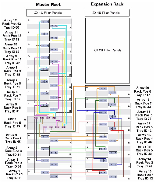
FIGURE B-18 Cabling for Twenty Expansion Trays

FIGURE B-19 Cabling One Controller Tray and Twenty Four Expansion Trays
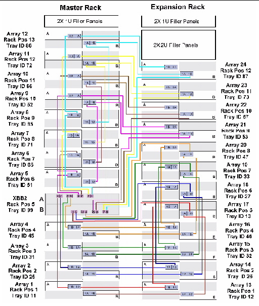
FIGURE B-20 Cabling for One Controller Tray and Twenty Four Expansion Trays
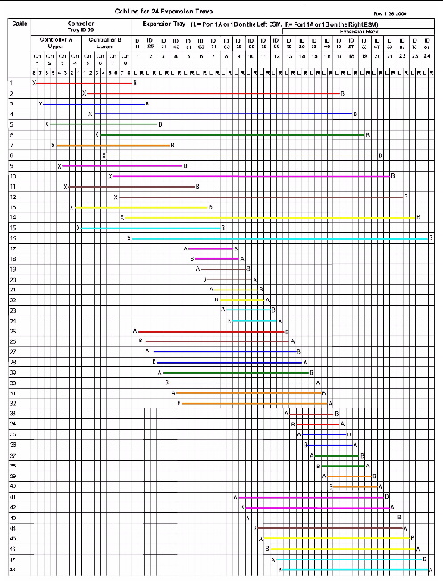
FIGURE B-21 Cabling One Controller Tray and Twenty Eight Expansion Trays

FIGURE B-22 Cabling for One Controller Tray and Twenty Eight Expansion Trays (1 of 2)

FIGURE B-23 Cabling for One Controller Tray and Twenty Eight Expansion Trays (2 of 2)

To set the tray link rate for an expansion tray:
1. Determine the speed of the disk drives in the tray.
a. Remove one of the disk drives and examine its label.
b. Next to the disk name on the label is a number indicating the RPM and speed of the disk. For example, the number 15k.4 indicates the disk is 15,000 RPMs and 4 Gbytes.
2. If the disk speed rate is 4 Gbits/second, verify that all expansion cables and SFPs are rated at 4 Gbits/second.
| Note - Change the position of a Tray Link Rate switch only when the tray is powered off. If you change the setting after power up, you must power cycle the tray. |
3. Locate the Tray Link Rate switch at the lower right front of the expansion tray.
FIGURE B-24 Expansion Tray Link Rate Switch

4. Set the default link rate for the tray as follows:
1. Verify that both power switches are off for each tray in the cabinet.
2. Connect each power supply in the tray to a different power source in the cabinet.
3. Connect the power cables from the cabinet to the external power source.
| Note - The power-on sequence is described in Powering On the Array. |
After installing and cabling the trays, you are ready to connect the management and data hosts, as described in Chapter 3.
| Hardware Installation Guide for Sun Storage 6580 and 6780 Arrays | 820-5773-11 |
Copyright © 2009 Sun Microsystems, Inc. All rights reserved.