|
Upgrading the Hardware |
Upgrading a StorageTek 6540 array to a Sun Storage 6580 array or a Sun Storage 6780 array enables you to use the new controller tray hardware features as well as the new controller firmware capabilities.
| Note - The StorageTek 6540 array must be at controller firmware level 7.1x or higher, and must have an optimal status prior to doing this upgrade. |
The upgrade process consists of the following steps.
| Note - Upgrading controller hardware is an offline procedure. The storage array is not able to receive I/O from the hosts when the new firmware is being activated. |
1. Turn off the power. See Turn Off the Power.
2. Disconnect and label signal cables and power cords. See Remove and Label Cables.
3. Remove the 6540 controller tray. See Remove the Old Controller Tray.
4. Install the 6580 or 6780 controller tray. See Install the New Controller Tray.
5. Reconnect the FC cables. See Reconnect the Cables and Cords.
6. Update the management software for the new controller. See Register the New Array and Reset the Battery Age.
| Note - If you have any problems during this upgrade, contact customer support. For support information, see http://www.sun.com/support/. |
|
1. Stop all I/O activity to the modules.
Wait for all data communications to cease before turning off the power. Refer to the Cache Active LED description in the installation guide for more information.
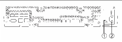
2. Turn off the power switch [1] on each controller module.
3. Turn off the power switch on each drive tray I/O module.
FIGURE 1 6540 Controller Tray AC Power Switch and AC Power Connector
|
1. At the AC power connector [2], disconnect the two power cords from the controller tray (one from each controller module). See FIGURE 1.
2. Disconnect and label (as necessary) FC and management cables from the controller tray.
Identify the controller (A or B) and the host port that each cable connects to. Controller A is on top, and controller B is on the bottom.
| Note - The expansion port cables need to be repositioned to match the new controller layout. Refer to your hardware cabling documents when needed. |
|
The following steps describe how to remove the controller tray from the cabinet.
1. Remove the controller tray’s front bezel.
2. Use the #2 Phillips screwdriver to loosen and remove the screws that fasten the controller tray to the cabinet.

|
Caution - The tray can weight up to 95 lbs (45 kg). Use at least two people to remove the tray from the cabinet. Remove components from the controller tray to reduce the weight if necessary. |
3. With one person on each side of the controller tray, gently pull the controller tray half-way out from the cabinet. Then with each person holding and lifting a side, remove the tray from the cabinet.
|
| Note - Static electricity is potentially hazardous to electronic circuitry. Handling of electronic components should be done in a static-free environment. |
1. Unpackage the new 6580 or 6780 controller tray.
You will install the new controller tray into the empty slot that was made available when removing the 6540 controller tray from the array.

|
Caution - The tray can weight up to 95 lbs (45 kg). Use at least two people to lift the tray into place. Remove components to reduce the weight if necessary. |
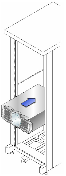
2. Using two people, one at each side of the tray, carefully lift and slide the tray evenly onto the bottom supporting ledge of the left and right rails.
Make sure to slide the tray all the way back into the cabinet. See FIGURE 2.
FIGURE 2 Controller Tray Installation
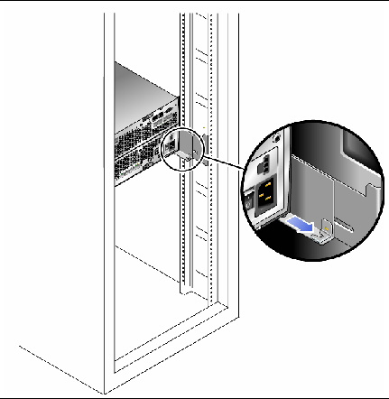
3. Make sure that the rear of the tray fits into the rear clasp. See FIGURE 3.
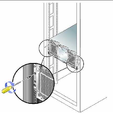
4. Using a #2 Phillips screwdriver and the screws removed earlier, secure the front of the controller tray to the cabinet’s vertical rail. See FIGURE 4.
FIGURE 4 Securing the Front of the Tray
|
You now have a Sun Storage 6580 or 6780 array with either four or eight host interface ports (using one or two Host Interface Cards (HICs)) and eight drive expansion ports. The following cabling scheme is recommended for your initial setup.
| Note - In some cases, the host ports at the end (Host 2, Channel 4) are used or reserved for Remote Replication. |
1. Plug in the host interface cables as described in TABLE 1.
If you now have eight host ports per controller, you can skip some ports to spread the workload across more of the available circuitry.
2. Plug in the drive expansion cables as described in TABLE 1.
FIGURE 5 Host and Expansion Port Locations Controller A and B
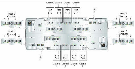
3. Plug in management host connections as needed.
4. Plug in the AC power cord for each controller module. See FIGURE 6.
| Note - The power cords must be plugged into different power distribution units to maintain power redundancy. |
FIGURE 6 AC Power Connectors on the Controller Tray
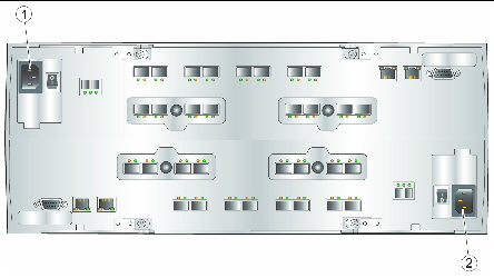
The hardware upgrade to a Sun Storage 6580 array or a Sun Storage 6780 array is complete. At this point, however, you might want to modify your drive expansion tray configuration.
5. To reconfigure the backend cabling, refer to Appendix B of the Hardware Installation Guide for Sun Storage 6580 and 6780 Arrays. Otherwise, or when done with the reconfiguration, use your installation documentation to do the following.
|
After the new hardware is installed, log into Sun Storage Common Array Manager and:
1. Unregister and then re-register the array to get the host to properly communicate with the new Sun Storage 6580 or 6780 array.
2. Go to Service Advisor, and follow the steps for resetting the battery age for the new controller.
Copyright © 2010, Oracle and/or its affiliates. All rights reserved.