x86: Sun Cluster Topologies
A topology is the connection scheme that connects the cluster nodes to the storage platforms that are used in the cluster. Sun Cluster supports any topology that adheres to the following guidelines.
-
Sun Cluster software supports from one to eight Solaris hosts in a cluster. Different hardware configurations impose additional limits on the maximum number of hosts that you can configure in a cluster composed of x86 based systems. See x86: Sun Cluster Topologies for the supported host configurations.
-
Shared storage devices must connect to hosts.
Sun Cluster does not require you to configure a cluster by using specific topologies. The following clustered pair topology, which is a topology for clusters that are composed of x86 based hosts, is described to provide the vocabulary to discuss a cluster's connection scheme. This topology is a typical connection scheme.
The following section includes a sample diagram of the topology.
x86: Clustered Pair Topology
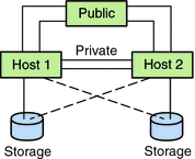
A clustered pair topology is two Solaris hosts that operate under a single cluster administrative framework. In this configuration, failover occurs only between a pair. However, all hosts are connected by the cluster interconnect and operate under Sun Cluster software control. You might use this topology to run a parallel database or a failover or scalable application on the pair.
The following figure illustrates a clustered pair configuration.
Figure 2–10 x86: Clustered Pair Topology

x86: N+1 (Star) Topology
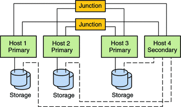
An N+1 topology includes some number of primary Solaris hosts and one secondary host. You do not have to configure the primary hosts and secondary host identically. The primary hosts actively provide application services. The secondary host need not be idle while waiting for a primary host to fail.
The secondary host is the only host in the configuration that is physically connected to all the multihost storage.
If a failure occurs on a primary host, Sun Cluster fails over the resources to the secondary host. The secondary host is where the resources function until they are switched back (either automatically or manually) to the primary host.
The secondary host must always have enough excess CPU capacity to handle the load if one of the primary hosts fails.
The following figure illustrates an N+1 configuration.
Figure 2–11 x86: N+1 Topology

- © 2010, Oracle Corporation and/or its affiliates
