| SPARC Enterprise M4000/M5000 Servers Overview Guide |
| C H A P T E R 1 |
|
System Overview |
This chapter provides information on the hardware and software features and configurations for the SPARC Enterprise M4000/M5000 midrange servers. This chapter contains these sections.
Both midrange servers are based on the SPARC64 VI/SPARC64 VII/SPARC64 VII+ processors.
FIGURE 1-1 M4000 Server [left] and M5000 Server [right] (Front Views)

TABLE 1-1 provides features for fully configured servers. For more detailed specifications on each component, see Components. For specifications of equipment racks, refer to the technical information manual for your equipment rack.
|
2 CPU modules, 8 processor cores |
4 CPU modules, 16 processor cores Type: SPARC64 VII/SPARC64 VII+ |
|
|
RFID tag[1] |
Financial Services Technical Consortium (FSTC) compliant EPC pre-programmed Frequency: 860-960 MHz[2] Read range: 1.8m (6ft) fixed reader/ 90cm (3ft) hand-held[3] |
|
The environmental requirements listed in TABLE 1-2 reflect the test results of the server. The optimum conditions indicate the recommended operating environment. Operating the server for extended periods at or near the operating range limits or installing the server in an environment where it remains at or near the non-operating range limits could possibly increase the failure rate of hardware components significantly. In order to minimize the occurrence of system failure due to component failure, set temperature and humidity in the optimal ranges.
|
Relative
|
|||
|
Altitude
|
|||
|
5˚C to 35˚C (41˚ F to 95˚F):
5˚C to 33˚C (41˚ F to 91.4˚F):
5˚C to 31˚C (41˚ F to 87.8˚F):
5˚C to 29˚C (41˚ F to 84.2˚F):
|
| Note - In order to minimize any chance of downtime due to component failure, use the optimal temperature and humidity ranges. |
Both midrange servers have these features:
The M4000 server is a six-rack unit (6 RU) enclosure (10.35 inches, 263 mm), which supports up to two dynamic server domains. FIGURE 1-2 and FIGURE 1-3 illustrate the components. See Components for a brief description of each component.
FIGURE 1-2 M4000 Server (Internal Front View)

FIGURE 1-3 M4000 Server (Internal Rear View)

|
I/O unit--supports one PCI-X slot (lowest slot) and four PCI Express slots (four upper slots) |
The M5000 server is a ten-rack unit (10 RU) enclosure (17.25 inches, 438 mm), which supports up to four dynamic server domains. FIGURE 1-4 and FIGURE 1-5 illustrates the components. See Components for a brief description of each component.
FIGURE 1-4 M5000 Server (Internal Front View)

FIGURE 1-5 M5000 Server (Rear View)

|
Each I/O unit supports one PCI-X slot (lowest slot) and four PCIe slots (four upper slots) |
The operator panel, which is identical for both midrange servers, is located on the front of the server in the upper right corner. The operator panel is used for the following tasks:
See Operator Panel for a description of the LEDs and status indicators.
For complete details on the operator panel controls, refer to the SPARC Enterprise M4000/M5000 Servers Service Manual.
The components of both midrange servers are described in the following sections:
TABLE 1-3 identifies the FRU components. Components using “hot FRU replacement” can be removed from the server and replaced while the operating server is running without performing a dynamic reconfiguration operation. Components using “active FRU removal” must be dynamically reconfigured out of the domain before removing the component.
|
Bus bar, I/O backplane, and power backplane unit (M5000 server) |
||||
The motherboard unit (FIGURE 1-6) is the main circuit board in both midrange servers. The following components connect to the motherboard unit:
To remove and replace the motherboard and these components, you must power the server off. For more details on the motherboard unit, refer to the SPARC Enterprise M4000/M5000 Servers Service Manual.
FIGURE 1-6 Removing the Motherboard Unit From the M5000 Server

Each CPU module contains SPARC64 VI processors or SPARC64 VII/SPARC64 VII+ processors. Each processor chip incorporates and implements the following:
The CPU modules can be accessed from the top of the midrange server. FIGURE 1-7 and FIGURE 1-8 illustrate the number of CPU modules per midrange server and their location. TABLE 1-4 lists features of the CPU modules. For additional information on the CPU module, refer to the SPARC Enterprise M4000/M5000 Servers Service Manual.
FIGURE 1-7 CPU Modules in the M4000 Server

FIGURE 1-8 CPU Modules in the M5000 Server

Each memory board provides a memory access controller (MAC) and eight DIMM slots (FIGURE 1-9 and FIGURE 1-10). To remove or install memory boards, you must power the server off. TABLE 1-5 lists the memory board features.
To install DIMMs, you must remove the memory board and open the case of the memory board. The servers use Double Data Rate II (DDR-II) type memory with the following features:
FIGURE 1-9 and FIGURE 1-10 illustrate the location of the memory boards in both midrange servers.
FIGURE 1-9 Memory Board Location in the M4000 Server

FIGURE 1-10 Memory Board Location in the M5000 Server

Both midrange servers use 172-mm fan units as the primary cooling system. The M4000 server also use two 60-mm fans. FIGURE 1-11 and FIGURE 1-12 illustrate the number of fans per midrange server, fan location, and the fan types used in both midrange servers.
The fan units in both midrange servers move air currents into and out of the server. The fans in both midrange servers are redundant. Because of the redundancy, system operation continues when a failure occurs with one fan. If the midrange server has two fans of each fan type, one fan of each fan type is redundant. If the midrange server has a total of four fans, two of the four fans are redundant (FIGURE 1-11 and FIGURE 1-12). Fan failures can be detected by the eXtended System Control Facility (XSCF).
The fans are accessed from the top of the midrange server.
FIGURE 1-11 and FIGURE 1-12 show the fan unit locations in both midrange servers.
FIGURE 1-11 Fan Unit Locations in the M4000 Server

FIGURE 1-12 172-mm Fan Unit Locations in the M5000 Server

Power is provided to both midrange servers by power supply units (FIGURE 1-13 and FIGURE 1-14).
FIGURE 1-13 Power Supply Units in the M4000 Server

FIGURE 1-14 Power Supply Units in the M5000 Server
The redundant power supplies allow continued server operation if a power supply fails. You can remove a power supply by way of active replacement, cold replacement, or hot replacement.
TABLE 1-6 lists the power supply features and some specifications. For additional specifications, refer to the SPARC Enterprise M4000/M5000 Servers Site Planning Guide.
This section describes the CPU types and the maximum power consumption of the server.
There are four types of CPU. The power specifications of the M4000/M5000 servers vary depending on the CPU type and the system configuration.
TABLE 1-7 and TABLE 1-8 list the specifications of maximum power consumption, apparent power, and heat dissipation by the type of CPU. The figures represent the system configuration described below the table, in which every CPU Modules (CPUM) is mounted with the same CPU.
| Note - Values in TABLE 1-7 and TABLE 1-8 are rounded to the nearest whole number. |
The operator panel (FIGURE 1-15), which is not redundant, displays the system status, system problem alerts, and location of system faults. It also stores the system identification and user setting information. For more information on the operator panel functions, refer to the SPARC Enterprise M4000/M5000 Servers Service Manual.

During startup, the front panel LED status indicators are individually toggled on and off to verify that each component is working correctly. After startup, the front panel LED status indicators operate as described in TABLE 1-9.
|
|
|||
|
|
|||
|
|
|||
|
|
|||
|
|
|||
|
|
LED status indicators are located on some of the FRUs. For information about LED status indicator locations, refer to the SPARC Enterprise M4000/M5000 Servers Service Manual.
|
The system is waiting for power-on of the air conditioning system. |
|||
|
Warm-up standby processing is in progress (power-on is delayed). |
|||
The eXtended System Control Facility Unit (XSCFU) is a service processor that operates and administrates both midrange servers (FIGURE 1-16 and FIGURE 1-17). The XSCFU diagnoses and starts the entire server, configures domains, offers dynamic reconfiguration, as well as detects and notifies various failures. The XSCFU enables standard control and monitoring function through network. Using this function enables starts, settings, and operation managements of the server from remote locations.
FIGURE 1-16 XSCFU Location in the M4000 Server

FIGURE 1-17 XSCFU Location in the M5000 Server

The XSCFU uses the eXtended System Control Facility (XSCF) firmware to provide the following functions:
Both midrange servers have one XSCFU, which is serviced from the rear of the server. To replace it, you must power off the server. For more information, refer to the SPARC Enterprise M4000/M5000 Servers Service Manual.
The XSCF firmware provides the system control and monitoring interfaces listed below.
The following additional interfaces for system control are also provided:
A UPS unit is used to provide a stable supply of power to the system in the event of a power failure or an extensive power interruption. By connecting the UPC port of the server and a UPS which has a UPC interface via signal cables, you can execute emergency shutdown processing when the commercial AC power supply failure detected.
This is dedicated for use by field engineers and cannot be connected to general-purpose USB devices.
The I/O unit is illustrated in FIGURE 1-18 and FIGURE 1-19. Four PCIe buses are connected from one I/O controller. These buses support all of the systems on-board I/O controllers in addition to the interface cards in the server.
FIGURE 1-18 I/O Unit Location in the M4000 Server
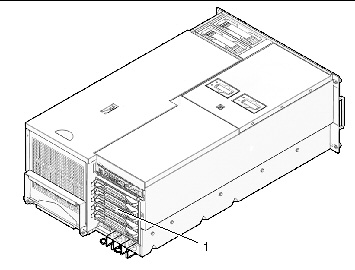
Figure showing the location of the I/O unit in the SPARC Enterprise M4000 server.
FIGURE 1-19 I/O Unit Locations in the M5000 Server

The I/O unit (IOU) is used in both the midrange servers. Refer to the SPARC Enterprise M4000/M5000 Servers Service Manual for more information on the IOU.
The IOU holds cassettes that support four PCIe cards and one PCI-X card.
The PCIe features include a high-speed serial point-to-point interconnect. Compared with conventional PCI buses, the PCIe data transfer rates are doubled.
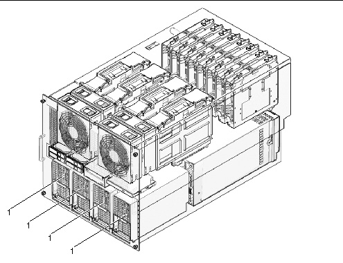
Both midrange servers provide front-panel access to the drives (FIGURE 1-20 and FIGURE 1-21). The following drives are provided on both midrange servers:
FIGURE 1-20 CD-RW/DVD-RW Drive Unit, Hard Disk Drive, and Tape Drive Unit in the M4000 Server

FIGURE 1-21 CD-RW/DVD-RW Drive Unit, Hard Disk Drive, and Tape Drive Unit in the M5000 Server
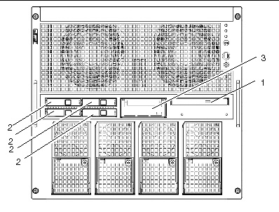
TABLE 1-11 lists the features, location, and specifications of the CD-RW/DVD-RW drive unit.
There are two types of CD-RW/DVD-RW drive units: tray load or slot load. Each type of drive unit will connect only with its corresponding drive unit backplane.
FIGURE 1-22 Two Types of CD-RW/DVD-RW Drive Units
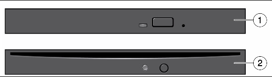
| Note - The locations of the LED and button might vary depending on the servers. |
The hard disk drives are located on the front of the midrange server. The SAS interface on the hard disk drive allows a fast data transmission rate.
The tape drive unit in both midrange servers is an optional component. TABLE 1-12 lists the features, location, and specifications of the optional tape drive unit.
Contact your sales representative for tape drive unit options on M4000/M5000 servers.
You can purchase an optional External I/O Expansion Unit to add I/O capacity to the server. For more information, refer to the External I/O Expansion Unit Installation and Service Manual.
Each PCI card in the server must be mounted to a PCI cassette before the card can be inserted into the I/O unit slot. For more information, see I/O Unit.
Oracle Solaris OS is installed on the system domains. In addition to its suite of software capabilities, Oracle Solaris OS provides functions that interact with system hardware.
Both midrange servers use the eXtended System Control Facility (XSCF) firmware. This firmware runs on the service processor and provides control and monitoring functions for the system platform.
For more information on the software features, see Chapter 3.
| SPARC Enterprise M4000/M5000 Servers Overview Guide | 819-2204-15 |
Copyright © 2007, 2010, Oracle and/or its affiliates. All rights reserved. FUJITSU LIMITED provided technical input and review on portions of this material.


