|
Lights Out Management Module |
The Lights Out Management (LOM) control module of the Sun Control Station software allows you to perform certain management and monitoring functions remotely on hosts that are compliant with the Intelligent Platform Management Interface (IPMI) Version 1.5. This document explains the features and services available through the Lights Out Management control module.
The LOM module implements functionality available within IPMI v1.5.
The sensors return the following environmental and status information:
For the LOM control module to function, the Linux kernel source RPM must be installed on the managed host on which you want to run the LOM functions.
The LOM control module includes a device driver that is compiled automatically when the module is installed on the managed host; the kernel source RPM is necessary for this device driver to compile successfully.
You do not need the Linux kernel source RPM if the managed host is running a Sun Linux distribution.
The LOM control module can run over either built-in network interface (eth0 or eth1) on a managed host. However, if both built-in network interfaces on a managed host are active, the managed host defaults to eth0.
When you click the Lights Out Management menu item, the submenu items enable you to configure host service processors to use LOM, perform power-on or power-off operations, view the sensor and SEL data from the managed host, or push global settings out to the service processors of managed hosts.
Some prospective managed hosts require service processor (SP) preconfiguration or manual post-installation configuration before the host can be managed properly by LOM module software.
The Sun Fire V60x, Sun Fire V65x, and Sun LX50 platforms require no preinstallation setup.
The service processors (SPs) of Sun Fire V20z and Sun Fire V40z systems must be preconfigured and must have the current BIOS and SP firmware installed. For instructions, see Preconfiguring the SPs of Sun Fire V20z and V40z Systems.
If the host is a Sun Fire LX50, Sun Fire V60x, or Sun Fire V65x, perform Auto Configuration as part of the LOM module installation. For instructions, see Auto-Configuring LOM on Sun LX50, Sun Fire V60x, and V65x Systems.
If the host is a Sun Fire V20z or a V40z system, you must configure the LOM manually. For instructions, see Manually Configuring LOM on Sun Fire V20z and V40z Systems.
For the Sun Fire V60x, Sun Fire V65x, and Sun LX50 family of machines, remote power-on sometimes fails to work. If you encounter this problem, enable the Gratuitous Arp feature in the LOM Settings screen. For details, see Settings.
1. Configure the Service Processor (SP) via the LCD front panel with a static IP address, subnet mask, and default gateway IP address.
For further instructions, refer to the section "Defining SP Network Settings" in the Sun Fire V20z and Sun Fire V40z Servers Installation Guide.
|
Note - You must use a different IP address than that of the host for the SP. The IP address must be static; LOM does not support DHCP-supplied IP addresses. |
2. Create the initial manager account for the SP.
This is necessary to enable logging in to the SP and running IPMI commands as described in the following steps.
For complete instructions, refer to the section "Creating the Initial Manager Account" in the Sun Fire V20z and Sun Fire V40z Servers Installation Guide.
3. (Optional) Set up the Server Management and Platform Software for the SP.
Refer to the "Server Management and Platform Software" section of the Sun Fire V20z and Sun Fire V40z Servers Installation Guide.
4. Determine whether your machine requires a BIOS update.
Use ssh to log in to the SP using the initial manager account defined in Step 2. When you log in, you will see something like the following:
Sun MicrosystemsIPMI v1.5 Service ProcessorVersion: V2.1.0.16
If the "Version" shown is V2.0.x.x, you MUST apply the BIOS and SP update.
5. (If necessary) Refer to the following website for the BIOS installation and accompanying instructions.
http://www.sun.com/servers/entry/v20z/downloads.html
http://www.sun.com/servers/entry/v40z/downloads.html
1. Select LOM  Configuration from the Sun Control Station interface.
You should see the newly added host. For a Sun Fire V20z or V40z system, the LOM Configured value will be N.
2. Select the host and click "Manual Configure."
The Configure Node Setting for LOM screen appears (see FIGURE 1).
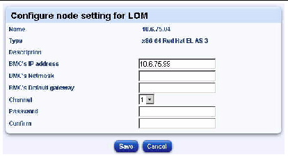
3. Supply IP configuration information.
|
Note - The BMC (baseboard management controller) is the same as the service processor (SP). This manual uses the latter term, but you may see the former in parts of the Sun Control Station interface. |
|
Note - If you are manually configuring LOM for a machine other than a Sun Fire V20z or a Sun Fire V40z, see TABLE 1 to determine the correct channel value. |
This command will first attempt to clear these values on the SP, then set them to the desired values. It may take a few minutes for the command to complete.
You should eventually see the LOM Configured value set to Y.
If, after executing all the steps above, LOM fails to work (that is, you cannot issue any commands to the managed host from LOM), refer to the section "IPMI Troubleshooting" in the Sun Fire V20z and Sun Fire V40z Servers Server Management Guide or contact your Sun service representative for assistance.
To configure LOM on the Sun LX50, Sun Fire V60x and V65x family of machines, perform these steps from the Sun Control Station interface.
2. Select the host in question.
This command will first attempt to clear these values on the SP, then set them to the desired values. It may take a few minutes for the command to finish running.
Normally, you should use the Auto-Configure feature to set up LOM on LX50, V60x, and V65x systems. However, if you should choose to configure LOM for these systems manually (see FIGURE 1), there are some issues of which you need to be aware.
1. The IP address, subnet mask, and default gateway address used for the service processor are those of the host machine.
2. You need to set the channel value according to the specific hardware, Ethernet interface used, and the version of the underlying Linux kernel. Refer to TABLE 1 to determine what channel setting to use.
The Lights Out Management Power submenu item allows you to perform power management functions on one or more managed hosts.
When you click on the Power submenu item, the selector window appears, displaying the groups and the managed hosts within each group. At the bottom of the selector window, the following buttons appear (see FIGURE 2).
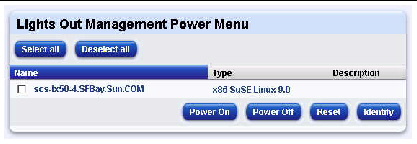
If you send the Power Off command to a managed host using the LOM module and then, in quick succession, send the Power On command (before the Power Off command is completed), the managed host may be left in an init 0 state: the host is still powered on but the operating system is shut down.
You can correct this problem by sending the Power Off command to the managed host again.
The Power On command allows you to power on a host remotely.
|
Note - If a host is already powered on, this command does not affect the host. |
1. Select Lights Out Management  Power.
The selector window appears, displaying the list of managed hosts.
2. Highlight one or more hosts, or click Select All to choose all hosts in the list.
3. Click Power On in the bottom right corner.
The Task Progress dialog appears.
The Power Off command allows you to power off a host remotely. This command attempts to shut down the operating system before turning off host power.
|
Note - If a host is already powered off, this command does not affect the host. |
1. Select Lights Out Management  Power.
The selector window appears, displaying the list of managed hosts.
2. Highlight one or more hosts, or click Select All to choose all hosts in the list.
3. Click Power Off in the bottom right corner.
The Task Progress dialog appears.
The Reset command causes a hardware reset. If the host is operating normally, the system shuts down elegantly and reboots. If the system is hung up and not responding, the Reset command will then force the system to reset.
|
Note - If the host is powered off, this command does not affect the host. |
1. Select Lights Out Management  Power.
The selector window appears, displaying the list of managed hosts.
2. Highlight one or more hosts, or click Select All to choose all hosts in the list.
3. Click Reset in the bottom right corner.
The Task Progress dialog appears.
On hosts that have an identifying LED, such as the Sun LX50 server or the Sun Fire V60x and V65x servers, the Identify command causes an LED to flash on the front panel and back panel; this is useful if you need to locate the host in an equipment rack.
The LED flashes for four minutes and then shuts off.
1. Select Lights Out Management  Power.
The selector window appears, displaying the list of managed hosts.
2. Highlight one or more hosts, or click Select All to choose all hosts in the list.
3. Click Identify in the bottom right corner.
The Task Progress dialog appears.
The Sensors/SEL submenu item allows you to view the most recent data from the sensors or the system event log (SEL) on the host, update the data in real time, or schedule an update of the data for a later time.
When you click on the Sensors/SEL submenu item, the selector window appears, displaying the groups and the hosts within each group. At the bottom of the selector window, the following buttons appear (see FIGURE 3).
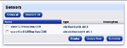
When you update the sensor and SEL information, the function retrieves the entire SEL from the managed host. A full SEL can contain as many as 3000 records. The updated SEL information in not displayed until the entire SEL is retrieved from the managed hosts.
The more entries that are contained in the SEL, and the more hosts from which you are retrieving SEL and sensor data, the longer it takes to retrieve that information. You should take these factors into account if you decide to schedule the updating of sensor and SEL information for a number of managed hosts.
You can view a summary of the sensor data for a host. From the resulting summary table, you can then view detailed tables of the sensor data, view the SEL and update the current data. This data is updated even if the host is powered off.
|
Note - Summary LOM sensor data from a managed host is also displayed in the Health Monitoring module. See Sensor Data in the Health Monitoring Module. |
1. Select Lights Out Management  Sensors/SEL.
A list of managed hosts appears.
2. Highlight one or more hosts, or click Select All to choose all hosts in the list.
The Sensor Status Summary table appears (see FIGURE 4).
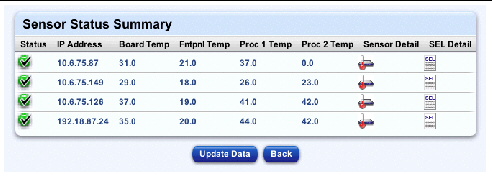
4. In the columns on the right side, you can do one of the following:
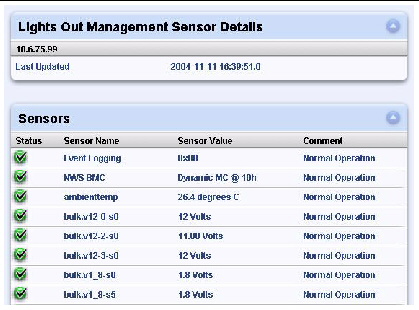
5. If you click on the Sensor Detail icon, a detailed sensor table appears.
Depending on the type of host, different sensors appear in this table (see FIGURE 5).
Click Update Data to update the sensor data (see Updating the Host Information Display).
6. Click on the System Event Log icon.
Records from the SEL appear (see FIGURE 6).
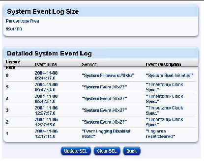
The Detailed System Event Log table displays the following information:
For more information on the event descriptions, refer to the IPMI documentation at
http://www.intel.com/design/servers/ipmi/index.htm.
From this screen, you can clear the SEL (see Clearing the SEL) or update the SEL (see Updating the SEL Display).
You can clear the SEL for a managed host. Once cleared, the SEL data is not recoverable. As this data may be needed by Sun Technical Support, take note of any unusual failure modes before clearing the SEL.
1. Go to the Detailed SEL table (see FIGURE 6).
2. Click the Clear SEL button.
This is located below the Detailed System Event Log table. The Task Progress dialog appears.
You can force the latest SEL data to be retrieved from the managed host.
1. Go to the screen displaying the detailed SEL tables.
2. Click the Update SEL button.
This is located below the Detailed System Event Log table. The Task Progress dialog appears.
|
Note - The Update Now feature in the Detailed System Event Log table updates the SEL information only. It does not update the sensor data. |
The Update feature allows you to retrieve the most recent sensor data and SEL on a managed host.
You can update the sensor data and SEL from a number of places in the UI:
 At the bottom of the selector window, click Update Now.
This feature updates all sensor data and SEL information for the managed hosts that you have selected.
 When viewing the Sensor Status Summary table, click Update Data.
This button is located below the table. Clicking the button updates the sensor data and SEL for each of the hosts listed in the Sensor Status Summary table.
 When viewing the detailed tables of sensor data, click Update Sensors.
This button is located below the tables. This feature updates all sensor data and SEL information for that particular host.
The Task Progress dialog appears.
In the Health Monitoring module, you can view detailed information tables of the state of components and services on a managed host.
When you view these tables for a host that reports LOM sensor data, the summary data appears in the Other System Services table. This data includes Sensors, System Event Log (SEL).
You can enter an email address in the Health Monitoring module so that someone receives alerts from the Health Monitoring module when there are critical system events (red circle).
For more information, refer to the PDF Sun Control Station 2.2 Health Monitoring Module.
The Settings screen (see FIGURE 7) enables you to push out common settings to the service processors for all managed hosts. These settings affect all hosts currently being managed by the Control Station, as well as those managed hosts you subsequently add.
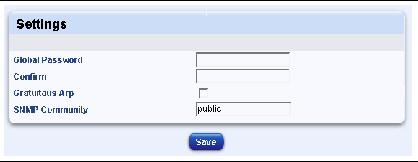
Service processor settings affected include the following.
|
Note - If you do not specify any local password for a host, and if you do not set a global password, the LOM module uses a default (random) password. |
IPMI defines common interfaces to "intelligent" hardware used to monitor a server's physical health characteristics and components, such as temperature, voltage, fans, power supplies, and chassis. In addition to health monitoring, IPMI includes other system-management capabilities such as automatic alerting, automatic system shutdown and restart, remote restart and power control capabilities, and asset tracking.
IPMI-based server management allows a user to determine the health of the server hardware, whether the server is running normally or is in a non-operational state. Servers based on IPMI use "intelligent" or autonomous hardware that remains operational even when the processor is down so that platform management information and control capabilities are always accessible. The robust and authenticated IPMI interfaces enable access to the same management capabilities from serial/modem, LAN, local management software, third-party emergency management add-in cards, and other IPMI-enabled servers under all system phases: power down, reboot, OS load, and run-time.
For more information on IPMI, refer to
http://www.intel.com/design/servers/ipmi/index.htm.
Copyright © 2004, Sun Microsystems, Inc. All Rights Reserved.