| Skip Navigation Links | |
| Exit Print View | |

|
Oracle VM Server for SPARC 2.0 Administration Guide |
1. Overview of the Oracle VM Server for SPARC Software
2. Installing and Enabling Software
4. Setting Up Services and the Control Domain
Introduction to a Virtual Network
Set Options for an Existing Virtual Switch
Managing a Virtual Network Device
Set Options for an Existing Virtual Network Device
Remove a Virtual Network Device
Virtual Device Identifier and Network Interface Name
Find Oracle Solaris OS Network Interface Name
Assigning MAC Addresses Automatically or Manually
Range of MAC Addresses Assigned to Logical Domains
Automatic Assignment Algorithm
Duplicate MAC Address Detection
Using Network Adapters With Logical Domains
Determine If a Network Adapter Is GLDv3-Compliant
Configuring Virtual Switch and Service Domain for NAT and Routing
Set Up the Virtual Switch to Provide External Connectivity to Domains
Configuring IPMP in a Logical Domains Environment
Configuring Virtual Network Devices Into an IPMP Group in a Domain
Configuring and Using IPMP in the Service Domain
Using Link-Based IPMP in Logical Domains Virtual Networking
Configure Physical Link Status Updates
Configuring and Using IPMP in Releases Prior to Logical Domains 1.3
Configuring IPMP in the Guest Domain
Configuring IPMP in the Service Domain
Assign VLANs to a Virtual Switch and Virtual Network Device
Install a Guest Domain When the Install Server Is in a VLAN
Configure a Virtual Switch With an NIU Network Device
Using Link Aggregation With a Virtual Switch
Configure Virtual Network and Virtual Switch Devices to Use Jumbo Frames
Compatibility With Older (Jumbo-Unaware) Versions of the vnet and vsw Drivers
12. Performing Other Administration Tasks
A. Oracle VM Server for SPARC Physical-to-Virtual Conversion Tool
B. Oracle VM Server for SPARC Configuration Assistant
C. Logical Domains Manager Discovery
D. Using the XML Interface With the Logical Domains Manager
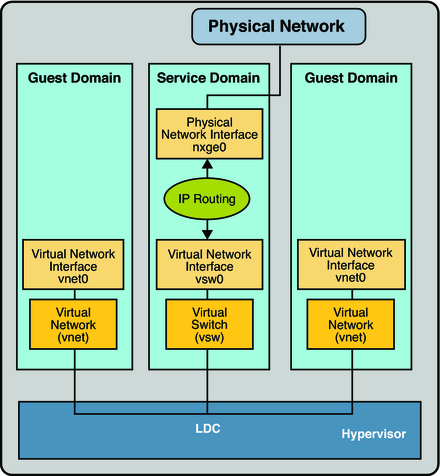
The virtual switch (vsw) is a layer-2 switch, that also can be used as a network device in the service domain. The virtual switch can be configured to act only as a switch between the virtual network (vnet) devices in the various logical domains but with no connectivity to a network outside the box through a physical device. In this mode, plumbing the vsw as a network device and enabling IP routing in the service domain enables virtual networks to communicate outside the box using the service domain as a router. This mode of operation is very essential to provide external connectivity to the domains when the physical network adapter is not GLDv3-compliant.
The advantages of this configuration are:
The virtual switch does not need to use a physical device directly and can provide external connectivity even when the underlying device is not GLDv3-compliant.
The configuration can take advantage of the IP routing and filtering capabilities of the Oracle Solaris OS.
Figure 8-2 Virtual Network Routing

If assigning an address, ensure that the virtual switch has an unique MAC address.
primary# ldm add-vsw [mac-addr=xx:xx:xx:xx:xx:xx] primary-vsw0 primary
See Configure the Virtual Switch as the Primary Interface for more information about plumbing the virtual switch.
See Configure the Virtual Switch as the Primary Interface for more information about configuring the virtual switch device for DHCP.
For information about how to do this, refer to Packet Forwarding and Routing on IPv4 Networks in System Administration Guide: IP Services.