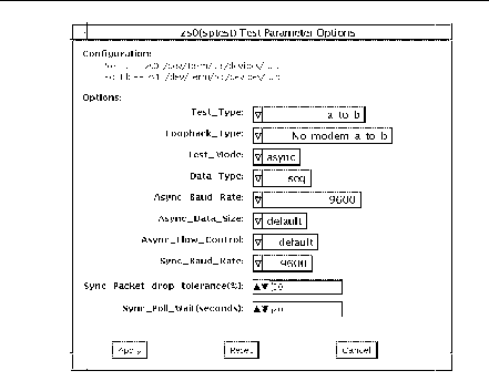
sptest Options
Figure 34-1 sptest Option Menu

There are a variety of loopback paths available. The internal loopback paths do not require an external connector. Their availability depends on the device. The zs(7D) device has an internal path for synchronous mode and the se(7D) device has an internal path for asynchronous mode. The external loopback connectors are described in Appendix A. The exact type of loopback connector required depends on the system I/O panel.
Legend: In the following table, a represents port a of the CPU board (motherboard), b represents port b of the CPU board, and the device names of the ports for each CPU board are listed.
Table 34-2 sptest Serial Devices|
CPU |
Port |
Async Device |
Sync Device |
|---|---|---|---|
|
0 |
a b |
zs0 or se0 zs1 or se1 |
zsh0 or se_hdlc0 zsh1 or se_hdlc1 |
|
1 |
a b |
zs2 zs3 |
zsh2 * zsh3 * |
|
2 |
a b |
zs4 zs5 |
zsh4 * zsh5 * |
|
* Currently, only zsh0 and zsh1 are supported by device drivers. |
|||
Table 34-3 sptest Options
|
sptest Options |
Description |
|---|---|
|
Test Type |
Selects how the test will run. Test options include: o a= runs the test on port a o b= runs the test on port b o a_b= runs the test on ports a and b sequentially o a_b_concurrent= runs the test on port a and port b concurrently. |
|
Test Mode |
Selects the mode to put the serial device into before running the test. The modes available are Asynchronous, Synchronous or Both. When Both is selected, the test runs in Asynchronous mode then Synchronous mode. |
|
Loopback Type |
Selects the loopback test. Options include: oInternal is an internal path for a, b, a_b, and a_b_concurrent test types. oPlug_a_to_a__b_to_b is an external loopback plug for a, b, a_b, and a_b_concurrent test types. ono_modem_a_to_b is an external loopback cable for a_to_b and a_to_b_concurrent test types. oModem_a_to_b is an external loopback cable with a modem attached to generate synchronous Transmit and Receive clocks in synchronous mode. The modem a_to_b external loopback type is intended for Sun internal use only. It requires custoe equipment that is not available. |
|
Data Type |
Selects the data pattern to transfer. The user can select: oRandom oSequential oAlphanumeric o0x00-0xff |
|
Async Baud Rate |
Selects the baud rate for Asynchronous mode testing. The valid rates are: 110, 300, 600, 1200, 4800, 9600, 19200, 38400, 57600, 76800, 115200, 153600, 230400, 307200, 460800, and ALL. The default rate is 9600 baud. Some platforms can only support up to 38400 or 76800. The test will return an error if you try to use a higher baud rate then is supported. For baud rates greater then 153600 the serial line drivers must be set for RS-423 mode and not RS-232 mode. The RS-423 and RS-232 modes are usually selected by a hardware jumper on the motherboard. Consult your hardware installation manual for more information. |
|
Async Block Size |
Selects the size (in bytes) of each write. This can range from 1 to 10000. The default is 100. If it is larger than the async size it will be truncated to the async size. |
|
Async Data Size |
Selects the total number of bytes to transfer in Asynchronous mode. This can range from 1 to 10000. |
|
Async Parity |
Selects the parity to use in asynchronous mode. The user can select even, odd, or none. The default is none. |
|
Async Flow Control |
Selects the type of flow control to use in asynchronous mode testing. The user can select Hardware (RTS/CTS), Software (XON/XOFF) or None. The default depends on the loopback type. Software flow control is not allowed on a, b, a_b, or a_b_concurrent loopback types. |
|
Sync Baud Rate |
Selects the device generated clock rate for synchronous mode testing. The valid rates are from 110 to 230400. The rate does not have to be a specific value as required for async mode baud rates. The default rate is 9600. Some platforms can only support up to 38400 or 76800. The test will return an error if you try to use a higher rate then is supported. For rates greater then 100000 the serial line drivers must be set for RS-423 mode and not RS-232 mode. The RS-423 and RS-232 modes are usually selected by a hardware jumper on the motherboard. Consult your hardware installation manual for more information. |
|
Sync Packet Drop Tolerance |
Selects the tolerance level of Synchronous mode dropped packets during the many_packets subtest. The default is 20 percent. The valid range is from 0 percent to 99 percent. Some packet drops are expected especially at higher clock rates and on a heavily loaded system. |
|
Sync Poll Count |
Selects the number of seconds in additional time to wait for a Synchronous mode packet to be sent. Additional time may be needed when there is heavy system activity and time-outs are being detected. In general, the user can decrease the value to 0 when the system load is light or increase the value when there is a heavy system load. |
- © 2010, Oracle Corporation and/or its affiliates
