| Exit Print View | |
Sun Datacenter InfiniBand Switch 72 User’s Guide |

|
Documentation, Support, and Training
Understanding Switch Specifications
Understanding InfiniBand Cabling
Understanding the Installation
Install the Switch in the Rack
Accessing the Management Controller
Access the Management Controller From the Network Management Port
Access the Management Controller From the USB Management Port
Verifying the InfiniBand Fabric
Administrative Command Overview
Monitoring the InfiniBand Fabric
Controlling the InfiniBand Fabric
Understanding Service Procedures
The power cords for the switch ship separately and are specific to the country of installation. The facility power receptacles for the power cords should be located such that the power cords are routed out of the way, either to the sides of the rack or under the floor.
When live power is delivered to the receptacles at the front of the chassis, standby and main power is made available by the power supplies. When standby power is distributed to the chassis, the management controller is powered on. The main power is supplied for the switch chips and fans.
Identify the prerequisite and subsequent installation tasks that you must perform in conjunction with this procedure.
Ensure that the circuit breakers for the power supplies are switched off.
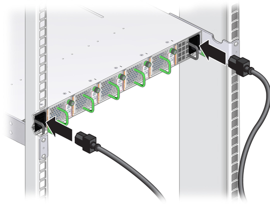
Plug a power cord into each power receptacle at the front of the chassis.

Route each power cord to its respective facility power receptacle.
Use cable ties or hook and loop fastener straps to bundle and secure the cord.
Plug each power cord into the receptacle.
Energize the circuit breakers so that the power receptacles are live.
Verify that the status LEDs for each power supply indicates normal operation.
The AC LED lights and in a moment, the OK LED should
light. The Attention LED should be unlit. See ![]() Check Power Supply Status LEDs.
Check Power Supply Status LEDs.
Note - At this time, power is being supplied to the management controller. The controller is effectively on and booting up. You might see the boot sequence on the management console.
Verify that the fans spin up.
You should feel air going into the fans and the fan Attention LEDs
should be unlit. See ![]() Check Fan Status LEDs.
Check Fan Status LEDs.
Verify that the chassis status OK LED lights.
Access the management controller.