Sun Blade X6270 Hardware and Software Features
|
This chapter summarizes the features available on the Sun Blade X6270 Server Module and contains the following topics:
1.1 Server Hardware and Software Features
TABLE 1-1 summarizes the standard configurations and optional components available for the Sun Blade X6270 Server Module.
TABLE 1-1 Server Hardware and Software Features
|
X6270 Server Module
|
Description
|
|
Standard Server Components Shipped
|
The following standard components are shipped on the Sun Blade X6270 Server Module:
- Service Processor (SP). One SP per server. SP provides remote KVMS functionality, IPMI baseboard management controller (BMC) functionality, and interfaces to the chassis monitoring module (CMM). The SPs and CMM work together to form a complete server module and chassis management system.
- Indicators and Buttons. The Sun Blade X6270 Server Module includes standard service indicator LEDs and buttons.
- Flexible I/O Network Connectivity. Supported I/O network connectivity can include these optional components: Fabric expansion module, chassis network express modules, and chassis PCI express modules.
- Front Panel I/O Device Connection. The Sun Blade X6270 Server Module front panel provides a universal connection port for attaching devices directly to the server using a dongle cable.
|
|
Preinstalled CPU and DIMM Configurations
|
Servers are typically ordered and shipped with preinstalled memory and CPU configurations. Some of the preinstalled memory and CPU assemblies offered (and shipped) for the Sun Blade X6270 Server Module can include:
- 2 Xeon Quad-Core E5520 CPU - 2.26GHz, Turbo, 80W
- 4GB Memory - 2x 2GB DDR3 1066MHz DIMMs
or
- 2 Xeon Quad-Core E5540 CPU - 2.53GHz, Turbo, 80W
- 12GB Memory - 6 x 2GB DDR3 1066MHz DIMMs
or
- 2 Xeon Quad-Core X5570 CPU -2.93GHz, Turbo, 95W
- 24GB Memory - 6 x 4GB DDR3 1333MHz DIMMs
|
|
Optional Server Components
|
The following optional server components may be ordered and shipped separately:
- CPU Assembly Options
- DDR3 Memory Kits
- Compact Flash
- SATA and SAS Hard Disk Drives (HDDs) and Solid State Drives (SSD)
- Dongle Cable Options (3-Cable Dongle or 4-Cable Dongle)
- Fabric Expansion Module (FEM) Options
- RAID Expansion Module (REM) Options
- Operating System Software
- Printed Documentation - Sun Blade X6270 Server Module Installation Guide.
Note - Server components and their part numbers are subject to change over time. For the most up-to-date list of replaceable components for servers, see the following URL: http://sunsolve.sun.com/handbook_pub/Systems/
- Click the name and model of your server.
- In the product page, click Full Components List for the list of components.
|
|
Supported Operating Systems
|
The following operating systems are supported on the Sun Blade X6270 Server Module.
- Microsoft Windows Server 2003 Enterprise Edition (R2 with SP2, or SP2) (32-bit and 64-bit)
- Microsoft Windows Server 2003 Standard Edition (R2 with SP2, or SP2) (32-bit and 64-bit)
- Microsoft Windows Server 2008, Standard Edition (32-bit or 64-bit)
- Microsoft Windows Server 2008, Enterprise Edition (32-bit or 64-bit)
- Microsoft Windows Server 2008, Datacenter Edition (32-bit or 64-bit)
- Red Hat Enterprise Linux (RHEL) 4.7, 32-bit and 64-bit
- RHEL 5.3, 64-bit
- SUSE Linux Enterprise Server (SLES) 10 SP2, 64-bit
- Solaris 10 10/08 and later
- VMware ESX and ESXi 3.5 Update 4
|
1.2 Server Indicators and Buttons
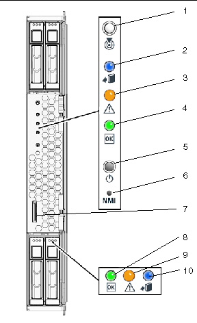
FIGURE 1-1 identifies the front panel buttons and indicators on the server.
FIGURE 1-1 Sun Blade X6270 Server Module Front Panel

Figure Legend Sun Blade X6270 Server Module Front Panel LEDs and Buttons
|
1
|
Server Locate LED
|
|
2
|
Server Ready-to-Remove LED
|
|
3
|
Server Service Action Required LED
|
|
4
|
Server OK Power LED
|
|
5
|
Server Power Button
|
|
6
|
Non-Maskable Interrupt (NMI) dump button (Service Only)
|
|
7
|
Universal connection port (UCP)
|
|
8
|
Storage device (hard disk drive or solid state drive) OK Power LED
|
|
9
|
Storage device Service Action Required LED
|
|
10
|
Storage device Ready-to-Remove LED
|

|
Caution - Do not use the NMI button unless you are instructed to do so by authorized Sun Service personnel. The NMI button sends an NMI dump request to the CPUs, which is used by Sun Field Service for debugging activities at the request of Sun Service personnel.
|
1.3 Attaching Devices To the Server
Your system chassis is shipped with a dongle cable that enables you to connect communication devices directly to the front panel of the Sun Blade X6270 Server Module.
The Sun Blade X6270 Server Module supports one of two types of dongle cables:
- 3-Cable Dongle II (P/N 530-3936 Option # 4622A). This cable provides a VGA connector, RJ-45 serial connector, and one dual USB connector.
- 4-Cable Dongle (P/N 530-3934 Option # 4621A). This cable provides a VGA connector, DB-9 serial connector, RJ-45 serial connector, and one dual USB connector.
| Note - The RJ-45 serial connector on the 4-Cable Dongle (Option# 4621A) is not functional on the Sun Blade Sun Blade X6270 Server Module. To establish a local serial connection with the Sun Blade X6270 Server Module, you should use the RJ-45 serial connector available on the 3-Cable Dongle (Option# 4622A) or the DB-9 serial connector on the 4-Cable Dongle.
|
| Note - The 3-Cable Dongle II is typically provided with each Sun Blade 6000 or 6048 Chassis System. Additional cables may be ordered.
|
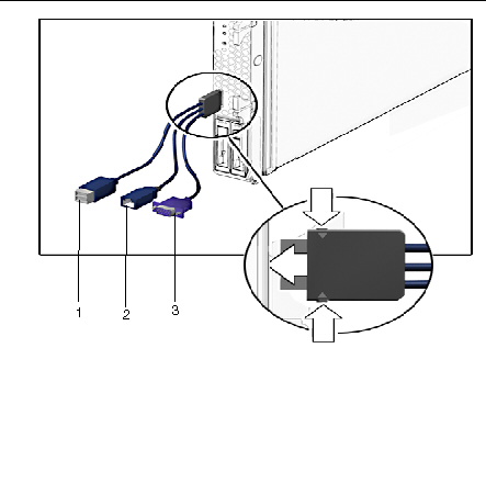
FIGURE 1-2 illustrates how to attach the 3-Cable Dongle to the Sun Blade X6270 Server Module universal connection port (UCP).
FIGURE 1-2 Server Front Panel I/O Connection Using 3-Cable Dongle

Figure Legend 3-Cable Dongle Connectors
|
1
|
Dual USB 2.0 connectors
|
|
2
|
RJ-45 Serial port connector
|
|
3
|
VGA video connector
|

|
Caution - The dongle cable should be used only for configuration and service purposes. It should be disconnected from the server module when the configuration or servicing operation is completed.
|
1.4 Replaceable Server Components
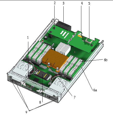
FIGURE 1-3 identifies the replaceable component locations on the Sun Blade X6270 Server Module, with the top cover removed.
FIGURE 1-3 Sun Blade X6270 Server Module Replaceable Component Locations

Figure Legend Replaceable Server Components
|
1
|
System battery
|
|
2
|
Fabric Expansion Module (FEM) (optional component)
|
|
3
|
Midplane connector
|
|
4
|
Raid Expansion Module (REM) (optional component)
|
|
5
|
Compact Flash Module (optional component)
The Compact Flash Module is shown in FIGURE 1-3 under the REM.
|
|
6a
|
DIMMs (optional components)
The DIMMs in FIGURE 1-3 are shown populated in DIMM slots 2, 5, 8 for each CPU.
Note - Processor chip contains memory controller. Do not attempt to populate DIMMs sockets next to unpopulated (empty) CPU sockets.
|
|
6b
|
DIMM filler panels
DIMM filler panels shown populated in DIMM slots 0, 1, 3, 4, 6 and 7.
Note - The DIMM filler panels should remain in unpopulated DIMM slots until the DIMM filler panel can be replaced with a DIMM. Otherwise, you may experience a reduction in system performance.
|
|
7
|
CPU heatsinks (up to two CPUs may be installed)
The minimum CPU configuration shipped includes one CPU with a heatsink. An air baffle is shipped to cover the empty CPU socket (not shown in FIGURE 1-3). Additional CPUs may be ordered.
Note - In the example shown in FIGURE 1-3, the CPUs are installed under the two heatsinks.
|
|
8
|
REM battery (optional component)
|
|
9
|
Storage devices (hard disk drives or solid state drives)
Up to four optional storage devices may be installed.
|
| Sun Blade X6270 Server Module Service Manual
|
820-6178-13
|
   
|
Copyright © 2010, Oracle and/or its affiliates. All rights reserved.


