| Sun StorEdge 3000 Family RAID Firmware 4.2x User's Guide |
| Sun StorEdge 3000 Family RAID Firmware 4.2x User's Guide |
| C H A P T E R 2 |
|
Basic Firmware Components |
This chapter introduces the initial firmware screen, menu structure, and navigation and screen conventions.
The Sun StorEdge 3310 SCSI array, Sun StorEdge 3320 SCSI array, Sun StorEdge 3510 FC array, and Sun StorEdge 3511 SATA array share the same firmware. However, the screens that are displayed and, to a lesser extent, the menu options vary between the different types of array. As a result, some of the examples in the manual might differ from what you see for your array.
Topics covered in this chapter include:
The initial firmware screen is displayed, as shown in FIGURE 2-1, when you power on the RAID controller and access the firmware application.
If an event message is displayed, press Escape after you read it to clear it from the screen or Ctrl-C to clear all messages.

The following table describes the components in the initial firmware screen.
|
Identifies the type of controller. This is also where the controller name entered using "view and edit Configuration parameters |
|
|
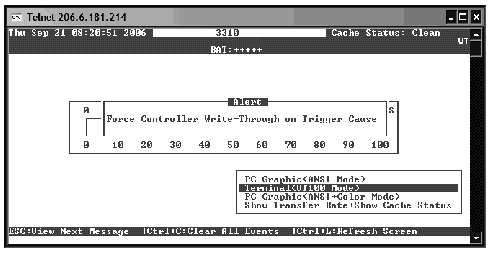
Indicates the percentage of controller cache that differs from what is saved to disk. "Clean" means that all cache has been saved to disk. "WT" indicates that an event trigger has disabled writeback cache and cache status is in write-through mode until the environmental event that caused the event trigger is corrected, at which time cache status will switch back automatically to writeback. See FIGURE 2-2. |
|
|
Battery status ranges from BAD to ----- (charging) to +++++ (fully charged). See Battery Operation. |
|
|
Indicates the current data transfer rate of communication between the array and the connected hosts. Select "Show Transfer Rate+Show Cache Status" from the list of screen display options and press + or - to increase or decrease the transfer rate Gauge range from its default of 10 Mbyte per second. |
|
|
Indicates the progress of various tasks as a percentage of completion. The percentage is preceded (?) by an abbreviation of the task being performed: |
|
|
Use + or - keys to change the gauge range of the transfer rate indicator when "Show Transfer Rate |
|
|
Explains the keyboard combinations that enable navigation of the interface. The up and down arrow keys, Enter (or Return), Ctrl-L, and the Escape key enable navigation. For details, see Illustration of an event trigger forcing a temporary write-through cache policyNavigating Firmware Menus. |
|
|
Changes the current data transfer rate of communication between the array and the connected hosts. With I/O running, select this display option, press Enter, and then press the + or - key to increase or decrease the transfer rate gauge range. |
If an array is connected to a host using a serial port connection and powered on, the host terminal window displays a series of messages, as shown in the following example.
If an event trigger is set to disable writeback cache, when it occurs the event message displays as an alert and the Cache Status: area of the initial firmware menu displays WT in the upper right corner. Performance might be decreased while this condition continues. Once the event that triggered the alert is corrected, cache policy reverts to its default setting.
To access the firmware menu options, use the up and down arrow keys to choose a screen display mode, and then press Return to enter the Main Menu.
The firmware menus described in this document, along with the steps you follow, are the same regardless of whether you have connected to the controller IP address using the telnet command, or through a serial port connection.
Once you have chosen the screen display mode, the Main Menu is displayed.

Use the following keys to navigate within the Main Menu and all its submenus.
If an array is connected to a host using a serial port connection and powered on, the host terminal window displays a series of messages, as shown in the following example.
Do not use the skip option shown at the bottom of the example. This option is reserved for support personnel performing testing.
|
Note - As you perform the operations described in this guide, you might periodically see event message pop up on the screen. To dismiss an event message after you've read it, press Escape. To prevent event messages for displaying so that you can only read them by displaying the event message log, press Ctrl-C. You can press Ctrl-C again at any time to enable pop-up displays of event messages. Viewing Event Logs on the Screen for more information about event messages. |
The firmware procedures use terminology and character conventions to indicate a sequence of steps, a specific menu option, or a series of menu options.
Some firmware menu options display their current state. For example, many of the Configuration Parameters resemble this one:
"Auto-Assign Global Spare Drive - Disabled"
When you choose a menu option that displays its current state, you are prompted to change it by choosing Yes or leave it in its current state by choosing No. If you choose Yes, the menu option now shows the new current state. The example now shows:
"Auto-Assign Global Spare Drive - Enabled"
This "toggle-switch" behavior applies to menu options that have only two states, typically Enabled and Disabled.
Progress indicators are displayed when necessary to indicate the percentage of completion of a particular task or event. The task might be represented by a descriptive title, such as Drive Copying, or by a prefix abbreviation.

Event messages showing full descriptive titles for the progress indicator include:
For other events, the progress indicator merely shows a two-letter code in front of the percentage completed. These codes and their meanings are shown in TABLE 2-4.
Firmware screens often present the capacity of devices such as logical drives. All device capacity is displayed in powers of 1024:
| Sun StorEdge 3000 Family RAID Firmware 4.2x User's Guide | 817-3711-18 |
Copyright © 2009, Dot Hill Systems Corporation. All rights reserved.


