| A P P E N D I X A |
|
Connectors |
This appendix describes the connectors that aid in testing communication ports.
Connectors aid in testing communications ports. The connectors take the form of either a single plug or a port-to-port cable with some communications connections shorted (looped-back).
The following table depicts the pin assignments for most plugs and cables that may be used when testing a system.
FIGURE A-1 shows the RS-232 and RS-423 single-port plug, which is a specially wired male DB-25 connector. Connect the plug to a serial port in the back of the system under test. The following table lists the pin connections for connecting the first plug to the second plug:
FIGURE A-1 25-pin RS-232 Plug Wiring Diagram

FIGURE A-2 shows how to connect 25-pin RS-232 and RS-423 port to 25-pin RS 232 and RS 423 port cables (two DB-25 connections). Connect the cable to a pair of serial ports in the back of the system under test. Both plugs are male. The following table lists the pin connections for connecting the first plug to the second plug:
FIGURE A-2 25-pin RS-232 Port-to-Port Cable Wiring Diagram
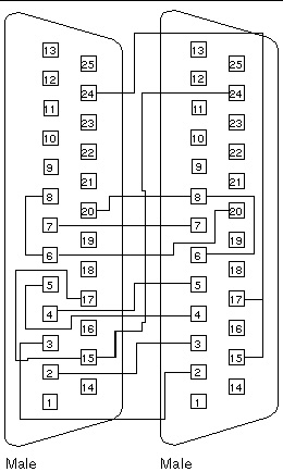
FIGURE A-3 shows how to connect 8-pin round DIN RS-232 port to RS-423 to 8-pin round-DIN RS-232 and RS-423 port cables. Both plugs are male. The following table lists the pin connections for connecting the first plug to the second plug:
FIGURE A-3 8-Pin to 8-Pin Cable Wiring Diagram
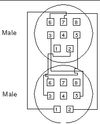
Pin 8, Receive clock In (DD), remains unconnected.
FIGURE A-4 shows how to connect male 8-pin round-DIN RS-232 and RS-423 single-port plugs. The following table lists the pin connections for connecting the first plug to the second plug:
FIGURE A-4 8-Pin Plug Wiring Diagram
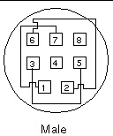
Pin 8, Receive Clock In (DD), remains unconnected.
FIGURE A-5 shows how to connect a 25-pin Port A to Port B plug for most systems. The following table lists the pin connections for connecting the first plug to the second plug:
FIGURE A-5 Port A-to-Port B Plug Wiring Diagram

If your system has a single communications port to connect it to peripherals, follow the connection instructions in FIGURE A-6 to make a male 25-pin plug for that communications port. The following table lists the pin connections for connecting the first plug to the second plug:
FIGURE A-6 Port A-to-A, Port B-to-B Plug Wiring Diagram

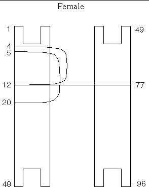
FIGURE A-7 shows a 96-pin connector that you can order from Sun (part number 370-1366). The following table lists the pin connections for connecting the first plug to the second plug:
The following are the materials used for this plug:
FIGURE A-7 96-Pin Female Connector Wiring Diagram
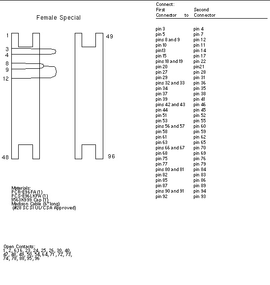
You can order this 96-pin connector from Sun (part number 370-1381).
FIGURE A-8 96-Pin Female Special Connector Wiring Diagram
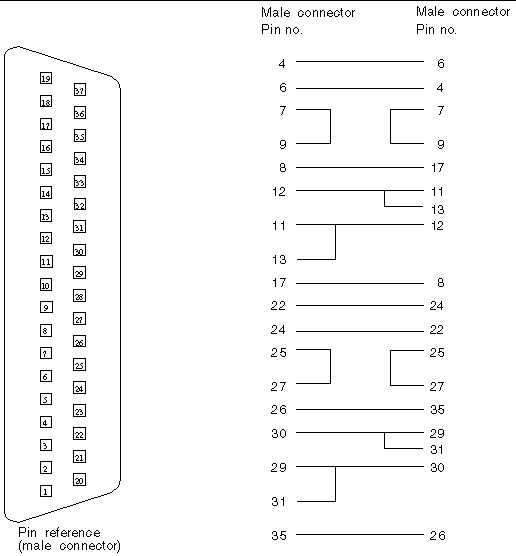
Use these wiring instructions for a cable for two 37-pin RS-449 synchronous ports.
FIGURE A-9 37-Pin RS-449 Cable Wiring Diagram
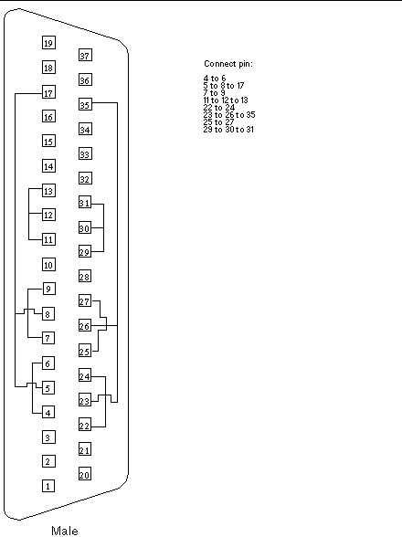
Use these wiring instructions to make a male 37-pin RS-449 plug. This plug is also available from Sun (part number 530-1430).
FIGURE A-10 37-Pin RS-449 Plug Wiring Diagram
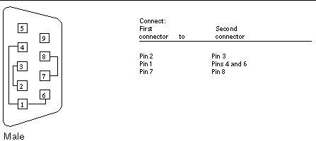
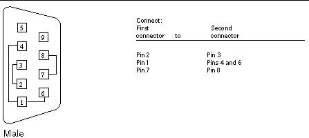
Use these wiring instructions for male 9-pin RS-232 and RS-423 single-port plugs.
FIGURE A-11 9-Pin Male Single-Port Plug Wiring Diagram
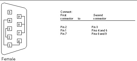
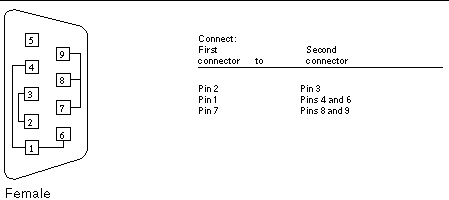
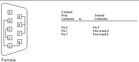
Use these wiring directions for female 9-pin RS-232 and RS-423 single-port plugs. Use this plug with the pcmciatest.
FIGURE A-12 9-Pin Female Single-Port Plug Wiring Diagram
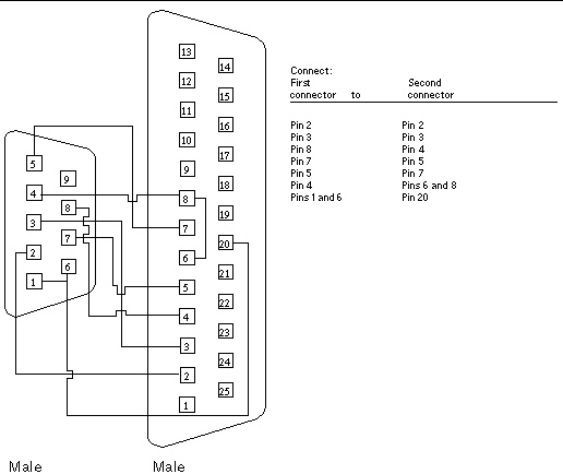
Use these wiring instructions for a 9-pin RS-232 and RS-423 port to 25-pin RS-232 and RS 423 port cables. Both connectors are male.
FIGURE A-13 9-Pin to 25-Pin Port-to-Port Cable Wiring Diagram
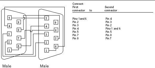
Use these wiring instructions for 9-pin RS-232 and RS 423 port to 9-pin RS-232 and RS-423 port cables. Both plugs are male.
FIGURE A-14 9-Pin to 9-Pin Port-to-Port Cable Wiring Diagram
This cable has no Sun part number assigned to it.
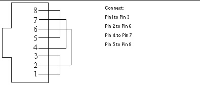
Using two standard RJ-45 connectors, and connect pin 1 to pin 1, pin 2 to pin 2, and so on, for all pins. This is a straight-through connection.
Use the following wiring instructions for standard RJ-45 connectors for Fast Ethernet. Use cable in netlbtest for eri devices.
FIGURE A-15 Twisted-Pair Ethernet (TPE) Cable Wiring Diagram for Fast Ethernet
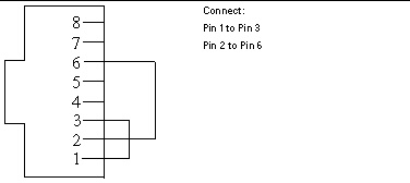
Use the following wiring instructions for RJ-45 plugs for Gigabit and 10/100 Ethernet. This cable is used in netlbtest for Gigabit and 10/100 devices.
FIGURE A-16 TPE Cable Wiring Diagram for Gigabit and 10/100 Ethernet
Use these wiring instructions for male 9-pin RS-232 and RS-423 single-port plugs.
FIGURE A-17 9-Pin Male Single-Port Plug Wiring Diagram
Use these wiring directions for female 9-pin RS-232 and RS-423 single-port plugs. Use this plug with the pcmciatest.
FIGURE A-18 9-Pin Female Single-Port Plug Wiring Diagram
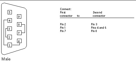
Use these wiring instructions for male 9-pin DB-9 external plugs.
FIGURE A-19 9-Pin Male DB-9 External Connector Wiring Diagram
The signals and names for the DB-9 connector are as follows.
Use these wiring instructions for female 9-pin DB-9 external connectors.
FIGURE A-20 9-Pin Female DB-9 External Connector Wiring Diagram
Copyright © 2010, Oracle and/or its affiliates. All rights reserved.