| Sun StorageTek ExpressModule SAS HBA Installation Guide |
| C H A P T E R 2 |
|
Hardware Installation and Removal |
The Sun StorageTek ExpressModule SAS HBA is packaged in a single-wide PCI ExpressModule. This chapter explains how to install the HBA in a PCI Express slot of an ExpressModule-compliant enclosure. You do not need to turn off system power or disconnect power cords during the installation, since these enclosures fully support hot-plugging.
This chapter contains the following topics:

|
Caution - Damage to the HBA can occur as the result of careless handling or electrostatic discharge (ESD). Always handle the HBA with care to avoid damage to electrostatic sensitive components. |
To minimize the possibility of ESD-related damage, use both a workstation antistatic mat and an ESD wrist strap. You can get an ESD wrist strap from any reputable electronics store or from Sun as part number #250-1007.
Observe the following precautions to avoid ESD-related problems:
Before you start, read the instructions in this section as well as the installation instructions for the storage devices to be connected to the HBA. This section contains the following topics:
|
1. Read and observe the safety information for this product.
See Safety Agency Compliance Statements.
2. Unpack the box containing the HBA in a static-free environment and inspect it for damage.
| Note - Leave the HBA in the protective bag until you are ready to install it. If there is damage, contact Sun customer support. |
|
1. Remove the cover from the system’s chassis.
2. Attach an antistatic wrist strap.
See Observing ESD and Handling Precautions.
3. Grasp the button at the top of the ejection lever on the front of the HBA and pivot the lever downwards.
4. Insert the HBA into an available PCI Express slot in the ExpressModule-compliant enclosure, as shown in FIGURE 2-1.
FIGURE 2-1 Installing the HBA into a PCI-E Slot

| Note - The configuration of the enclosure may not be the same as shown in this illustration. |
5. When the HBA is fully inserted in the slot, pivot the ejection lever up to the locked position.
6. Connect SAS cables to the two external x4 mini-SAS connectors and attach them to disk drives or other SAS/SATA devices, per your requirements.
Use only Sun-provided SAS cables (530-3887-01), available for purchase at http://www.sun.com..
The HBA hardware installation is complete.
The HBA has six LEDs that are visible on the end of the HBA. FIGURE 2-2 shows the external connectors and LEDs.
FIGURE 2-2 External Connectors and LEDs

The LEDs next to each mini-SAS connector adapter are green for Activity and yellow for Fault for the 4 PHYs associated with each SAS connector. The yellow Attention LED and green Power LED are next to the Attention button.
The states of the Attention and Power LEDs are listed in TABLE 2-1
|
Removal of the HBA is not permitted because a hot-plug operation is in progress. |
|
This section describes the various ways to test the installation in a Solaris enviroment. This section contains the following topics:
|
| Note - This procedure is not valid in a Solaris 10 for x64/x86 environment. Instead, use the format command to verify the installation of the HBA before attempting to use it in a Solaris 10 for x64/x86 environment. See To Test the Installation Using the Solaris format Command. |
1. Bring the system down to the ok prompt at run level 0.
| Note - If the host starts to reboot, interrupt the reboot process by pressing the Stop and A keys simultaneously. |
2. At the ok prompt, use the probe-scsi-all command to verify that the system recognizes the HBA.
The probe-scsi-all command displays the SCSI devices that are connected to the host, as shown in the following screen example.
This example shows two SAS controllers. The first (sas@2) is the SAS controller resident on the motherboard. The second SAS controller (sas@0) has one disk drive connected (Target 1). The disk consists of two logical unit numbers (LUNs), Unit 0 and Unit 1.
|
Use the following procedure to test the HBA installation using the format command on the Solaris 10 for x64/x86 platform.
1. Become a root user and use the format command.
2. When prompted, type the number of the disk drive that is attached to the HBA card you just installed and press Enter.
3. Type analyze to select the type of test.
4. Type read to further define the type of test, and then type y to continue.
5. Verify that no error occurred, as indicated by the output line Total of 0 defective blocks repaired.
6. Contact your service provider if an error occurs.
7. Type q twice to quit the test and the Format menu.
The Sun StorageTek ExpressModule SAS HBA is ready for use.
|
Use the SunVTS software to test a disk on a newly attached disk array to verify that the HBA is properly installed.
For details about running the SunVTS software, refer to the SunVTS 6.X User’s Guide and the SunVTS 6.X Test Reference Manual.
| Note - Refer to the SunVTS documentation to determine whether the host platform is supported. |
1. As superuser, open the SunVTS window.
2. From the System Map, select a disk drive that is in an array connected to the HBA.
4. Verify that no errors have occurred by checking the SunVTS status window.
| Note - If problems occur, contact your service provider for assistance. |
5. If no problems occur, stop the SunVTS software.
The HBA is now ready to run applications.
The Sun StorageTek ExpressModule SAS HBA uses the Solaris mpt device driver, which is included with Solaris patches 125082-16 (x64) and 125081-16 (SPARC). The patches are available for download at http://sunsolve.sun.com..
|
The BIOS initialization screen is displayed.
2. Immediately press Control-C.
The LSI Logic MPT SCSI Setup Utility menu is displayed.
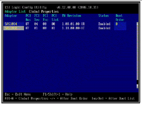
In this example, the first line (SAS1064) is the SAS controller that is resident on the motherboard. The HBA (SAS1068) is installed in PCI Express slot 01.
3. To change the boot options, use the arrow keys to move the grey highlighted field to the Boot Order field and use the following keys.
4. To change other options, move the grey highlighted field to the appropriate HBA, and press Enter.
Details for the selected adapter are displayed, as shown in the following example.
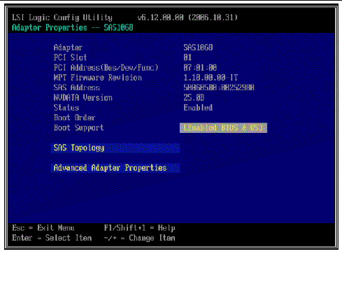
5. To view the devices attached to this adapter, highlight SAS Topology and press Return.
The following screen is displayed.
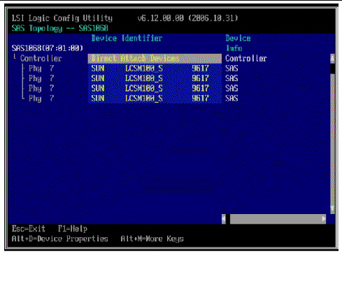
6. In this example, a single SAS RAID array is attached to the adapter. The array has four bonded PHYs.
7. To exit this screen, press the Escape key.
8. Use the arrow key to highlight Exit the Configuration Utility and press Enter.
9. Press any key to reboot the system.
Follow these steps to remove the HBA from an enclosure:
1. Prepare your operating system for HBA removal.
2. Disconnect all SAS cables from the external mini-SAS connectors.
3. Press the Attention button on the exposed end of the HBA (see FIGURE 2-2).
4. When the green Power LED next to the Attention button goes out, pull the ejection lever downwards.
5. Pull the HBA out of its slot in the enclosure.
| Sun StorageTek ExpressModule SAS HBA Installation Guide | 820-3214-11 |
Copyright © 2009 Sun Microsystems, Inc. All rights reserved.
 To Prepare for Hardware Installation