Configuration Examples
This section contains some examples of configuration files, based on the "Configuration Planning Example".
-
"IP-Transparent Mode Interface Configuration" shows an IP-transparent configuration.
-
"Server Mode Interface Configuration" shows the configurations for two interfaces, each configured in server mode.
-
"Logical Interfaces" shows the configuration for one interface that is configured as one logical interface at the IP level, using classes to divide the traffic by subnet.
-
"Complete Configuration" shows a complete configuration for the Paris site, including the standard service definitions.
IP-Transparent Mode Interface Configuration
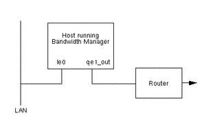
Figure 4-1 IP-Transparent Configuration at London Site

In IP-transparent mode, the host running Solaris Bandwidth Manager sits between the traffic source (usually a LAN) and the router. On the host shown in Figure 4-1, you configure the qe1_out interface for Solaris Bandwidth Manager, giving le0 as the network device. For example:
interface   qe0_out
            rate          512000
            activate      enabled
            router_addr   123.xxx.yyy.1
            network       le0
            router_mac    809xxxxx
            multicast     all
In addition to the configuration shown above, you must configure a standard IP interface for the network interface to the LAN. This is necessary for the interface to be inserted into the IP stack at boot time. Create the file /etc/hostname.interfacename with a reference to the IP address of the interface.
Note -
Do not configure the network interface on the WAN side. Run ifconfig -a and check that there is no reference to this interface.
Server Mode Interface Configuration
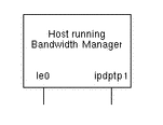
Figure 4-2 Interfaces Configuration at Paris Site

In this example, the host running Solaris Bandwidth Manager is acting as a router and there are two interfaces. le0 is the interface used when sending network traffic to London, and ipdptp1 is a PPP interface used when sending network traffic to Bonn. The configurations for both interfaces are normal server mode configurations. For example:
interface   le0_out
            rate       263144
            activate   enabled
interface   ipdptp1_in
            rate       65536
            activate   enabled
Logical Interfaces
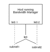
Figure 4-3 Configuring Logical Interfaces

Solaris Bandwidth Manager operates at the level of the physical interface (le0) and does not recognize logical interfaces (le0:1 and le0:2, for example). If your IP configuration includes logical interfaces, you can use the class hierarchy to subdivide network traffic according to the destination subnet, and then manage the traffic for each subnet separately. Figure 4-3 shows a configuration with two logical interfaces. The configuration file contains a definition for the le0 interface, and filter and class definitions for the subnet1 and subnet2 classes. For example:
filter    subnet1
          remote
                   type            subnet
                   address         123.xxx.yyy.0
                   mask            255.255.255.0

filter    subnet2
          remote
                   type            subnet
                   address         123.xxx.zzz.0
                   mask            255.255.255.0

interface le0
                   rate            263144
                   activate        enabled

class     subnet1
                   parent          root
                   interface       le0_in
                   bandwidth       60
                   priority        3
                   max_bandwidth   100
                   filter          subnet1

class     subnet2
                   parent          root
                   interface       le0_in
                   bandwidth       40
                   priority        3
                   max_bandwidth   100
                   filter          subnet2
Complete Configuration
The following file implements the configuration described for the Paris server in "Configuration Planning Example". Note that two filters, imap and smtp, have been used to define the class email.
# Sample configuration file for Paris site


version 1.6
timeout 30

#Subnet Group definitions

subnet_group bonn
        address         129.xxx.xxx, 129.xxx.yyy
        mask            225.225.225.0

subnet_group paris
        address         129.yyy.xxx, 129.yyy.yyy, 129.yyy.zzz
        mask            225.225.225.0

subnet_group london
        address         129.zzz.xxx, 129.zzz.yyy
        mask            225.225.225.0

#Filter definitions

filter http_to_london
        local
                type    subnet_group
                name    paris
        remote
                type    subnet_group
                name    london
        service         http

filter telnet
        service         telnet

filter imap
        service         imap

filter http_to_bonn
        local
                type    subnet_group
                name    paris
        remote
                type    subnet_group
                name    bonn
        service         http
filter snmp
        service         snmp

filter http
        service         http

filter ftp
        service         ftp

filter smtp
        service         smtp

#Interface defintions for qe0_out

interface qe0_out
        rate            128000
        activate        enabled


#Class definitions for interface qe0_out

class ftp
        interface       qe0_out
        parent          root
        filter          ftp
        bandwidth       15
        priority        7
        max_bandwidth   15

class email
        interface       qe0_out
        parent          root
        filter          imap, smtp
        bandwidth       20
        priority        7
        max_bandwidth   20

class snmp
        interface       qe0_out
        parent          root
        filter          telnet
        bandwidth       5
        priority        1
        max_bandwidth   5

class telnet
        interface       qe0_out
        parent          root
        filter          telnet
        bandwidth       30
        priority        1
        max_bandwidth   30

class http
        interface       qe0_out
        parent          root
        filter          http
        bandwidth       20
        priority        5
        max_bandwidth   20

class http_bonn
        interface       qe0_out
        parent          http
        filter          http_to_bonn
        bandwidth       5
        priority        3
        max_bandwidth   5

class http_london
        interface       qe0_out
        parent          http
        filter          http_to_london
        bandwidth       10
        priority        3
        max_bandwidth   10

class default
        interface       qe0_out
        bandwidth       0
        priority        7
        max_bandwidth   0

#Interface definition for qe0_in

interface qe0_in
        rate            128000
        activate        enabled

#Class definition for interface qe0_in

class default
        interface       qe0_in
        bandwidth       100
        priority        7
        max_bandwidth   100
|
- © 2010, Oracle Corporation and/or its affiliates
