| C H A P T E R 4 |
|
Installing the Sun StorageTek 5320 NAS Cluster Appliance |
This chapter provides comprehensive instructions for connecting the Sun StorageTek 5320 NAS Cluster Appliance, the Sun StorageTek 5320 RAID Controller Units (CUs), and the optional Sun StorageTek 5320 Expansion Units (EUs). It also provides initial configuration instructions for the system.
|
Note - The Sun StorageTek 5320 NAS Cluster Appliance ships with the operating system installed. |
|
Note - This chapter contains Sun StorageTek 5320 NAS Cluster Appliance connection and configuration instructions only. If you are connecting a different system, refer to the appropriate chapter. |
This chapter contains the following sections:
Before connecting the system, you must install the units in the rack. Refer to Installing Servers and Back-End Storage for rackmount instructions.
This section describes how to cable the Sun StorageTek 5320 NAS Cluster Appliance to the controller units and the controller unit to the optional expansion units for several different configurations.
This section includes the following tasks:
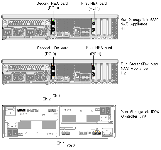
FIGURE 4-1shows the ports of a cluster appliance and controller units.
|
Note - HBA cards for storage connections are inserted only in PCI slot 1 (PCI1) and PCI slot 0 (PCI0) of each server in the Sun StorageTek 5320 NAS Cluster Appliance. |
This section contains details on the following:
Use the instructions in this section if you are connecting one controller unit to the Sun StorageTek 5320 NAS Cluster Appliance.
1. Connect the HBA port 1 (top port) of the first HBA card (PCI1) on the Sun StorageTek 5320 NAS Cluster Appliance H1 to the Controller A Ch 1 port.
The H1 and H2 cluster pairs are identifed by the software serial number located on a printed label at the front of the server. (See Sun StorageTek 5320 NAS Appliance Server.)
2. Connect the HBA port 1 of the second HBA card (PCI0) on the cluster appliance H1 to the Controller B Ch 1 port.
3. Connect the HBA port 1 of the first HBA card on the cluster appliance H2 to the Controller A Ch 2 port.
4. Connect the HBA port 1 of the second HBA card on the cluster appliance H2 to the Controller B Ch 2 port.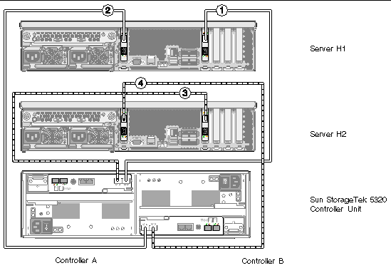
|
Note - The preceding figure is for illustrative purposes only. The units have more space between them when they are installed in a cabinet. |
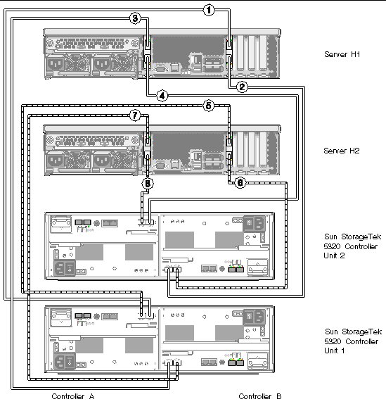
Use the instructions in this section and refer to FIGURE 4-3 if you are connecting two controller units to the Sun StorageTek 5320 NAS Cluster Appliance.
1. Connect the HBA port 1 (top port) of the first HBA card (PCI1) on the Sun StorageTek 5320 NAS Cluster Appliance server H1 to the Controller A Ch 1 port on the first (bottom) controller unit (Unit 1).
2. Connect the HBA port 2 of the first HBA card on the cluster appliance H1 to the Controller B Ch 1 port on the second (top) controller unit (Unit 2).
3. Connect the HBA port 1 of the second HBA card (PCI0) on the cluster appliance H1 to the Controller B Ch 1 port on Unit 1.
4. Connect the HBA port 2 of the second HBA card on the cluster appliance H1 to the Controller A Ch 1 port on Unit 2.
5. Connect HBA port 1 of the first HBA card (PCI1) on the cluster appliance H2 to the Controller A Ch 2 port on Unit 1.
6. Connect HBA port 2 of the first HBA card on the cluster appliance H2 to the Controller B Ch 2 port on Unit 2.
7. Connect HBA port 1 of the second HBA card (PCI0) on the cluster appliance H2 to the Controller B Ch 2 port on Unit 1.
8. Connect HBA port 2 of the second HBA card on the cluster appliance H2 to the Controller A Ch 2 port on Unit 2.
|
Note - The preceding figure is for illustrative purposes only. The units have more space between them when they are installed in a cabinet. |
Each controller unit uses Controller A and Controller B expansion ports to connect to FC-AL ports at the back of an expansion unit (FIGURE 4-4).
The cabling differs depending on the number of expansion units you are connecting:
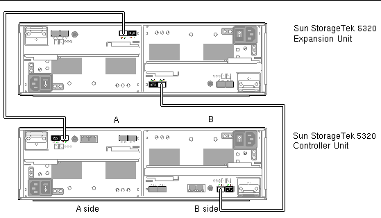
To connect a controller unit and one expansion unit, two 2-meter fiber cables are required. Refer to FIGURE 4-5.
1. Connect one fiber cable between the A side expansion port P1 of the controller unit and the A side port 1B of the expansion unit.
2. Connect one fiber cable between the B side expansion port P1 of the controller unit and the B side port 1B of the expansion unit.
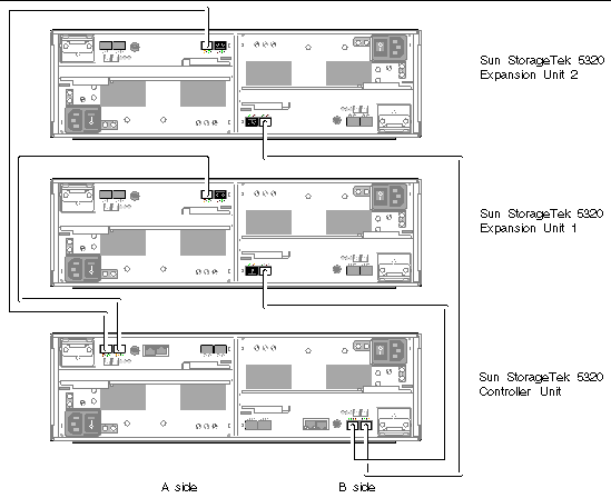
To connect a controller unit and two expansion units, four 2-meter fiber cables are required. Refer to FIGURE 4-6.
1. Connect one fiber cable between the A side expansion port P2 of the controller unit and the A side port 1B of expansion unit 2.
2. Connect one fiber cable between the A side expansion port P1 of the controller unit and the A side port 1B of expansion unit 1.
3. Connect one fiber cable between the B side expansion port P1 of the controller unit and the B side port 1B of expansion unit 1.
4. Connect one fiber cable between the B side expansion port P2 of the controller unit and the B side port 1B of expansion unit 2.
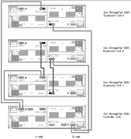
To connect a controller unit and three expansion units, six 2-meter fiber cables are required. Refer to FIGURE 4-7.
1. Connect one fiber cable between the A side expansion port P2 of the controller unit and the A side port 1B of expansion unit 3.
2. Connect one fiber cable between the A side expansion port P1 of the controller unit and the A side port 1B of expansion unit 1.
3. Connect one fiber cable between the A side port 1A of expansion unit 1 and the A side port 1B of expansion unit 2.
4. Connect one fiber cable between the B side expansion port P1 of the controller unit and the B side port 1B of expansion unit 2.
5. Connect one fiber cable between the B side expansion port P2 of the controller unit and the B side port 1B of expansion unit 3.
6. Connect one fiber cable between the B side port 1B of expansion unit 1 and the B side port 1A of expansion unit 2.
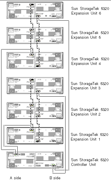
To connect a controller unit and six expansion units, twelve 2-meter fiber cables are required. Refer to FIGURE 4-8.
|
Note - In a configuration with two controller units, a maximum of four expansion units can be attached to each controller unit. |
1. Connect one fiber cable between the A side expansion port P2 of the controller unit and the A side port 1B of expansion unit 4.
2. Connect one fiber cable between the A side expansion port P1 of the controller unit and the A side port 1B of expansion unit 1.
3. Connect one fiber cable between the A side port 1A of expansion unit 1 and the A side port 1B of expansion unit 2.
4. Connect one fiber cable between the A side port 1A of expansion unit 2 and the A side port 1B of expansion unit 3.
5. Connect one fiber cable between the A side port 1A of expansion unit 4 and the A side port 1B of expansion unit 5.
6. Connect one fiber cable between the A side port 1A of expansion unit 5 and the A side port 1B of expansion unit 6.
7. Connect one fiber cable between the B side expansion port P1 of the controller unit and the B side port 1B of expansion unit 3.
8. Connect one fiber cable between the B side expansion port P2 of the controller unit and the B side port 1B of expansion unit 6.
9. Connect one fiber cable between the B side port 1B of expansion unit 1 and the B side port 1A of expansion unit 2.
10. Connect one fiber cable between the B side port 1B of expansion unit 2 and the B side port 1A of expansion unit 3.
11. Connect one fiber cable between the B side port 1B of expansion unit 4 and the B side port 1A of expansion unit 5.
12. Connect one fiber cable between the B side port 1B of expansion unit 5 and the B side port 1A of expansion unit 6.
Each server in a Sun StorageTek 5320 NAS Cluster Appliance uses a dedicated Ethernet connection to communicate with its partner and perform periodic "health checks." The port used for the health check connection is referred to as the heartbeat port. The NET0 Gigabit Ethernet port is used for the heartbeat.
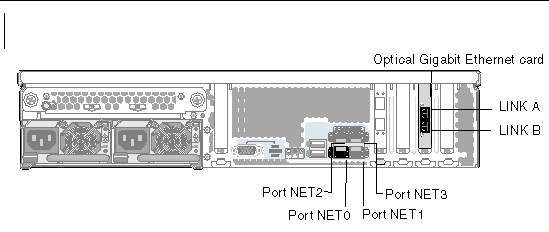
The Sun StorageTek 5320 NAS Cluster Appliance is commonly configured with two Gigabit Ethernet cards. FIGURE 4-9 shows a single card configuration.
|
 Use a Cat5 Ethernet cable to connect the two servers' NET0 heartbeat ports.
|
The appliance must be configured with a second optical Gigabit Ethernet card.
 Connect a fiber optic cable from the network to the top (LINK A) and connect another fiber optic cable from the network to the bottom (LINK B) optical Gigabit Ethernet connector on the back of each of the Sun StorageTek 5320 NAS Cluster Appliances.
Later, when you configure the system (see Initial Sun StorageTek 5320 NAS Cluster Appliance Configuration), the ports will be identified on the LCD as shown in TABLE 4-1.
|
If your system is configured for Fast Ethernet or Gigabit Ethernet networking, refer to FIGURE 4-9 for NIC port locations.
 To connect the Sun StorageTek 5320 NAS Cluster Appliance to a Fast Ethernet or Gigabit Ethernet network, connect an RJ-45 unshielded twisted-pair cable from your local area network (LAN) to the NET1 port on the back of each of the Sun StorageTek 5320 NAS Cluster Appliances. For additional LAN connections, continue to connect in order: NET2 and NET3.
This section describes how to power on the appliance, controller units, and expansion units for the first time. It also details how to power on the system after the initial power-on sequence.

|
Caution - You must follow the correct initial power-on sequence for your configuration. Failure to follow the correct procedure will result in an inoperative system. |
|
Note - If you are using a UPS, connect all units to the UPS. |
|
Note - To achieve fault tolerance, units with two power supplies must receive power from two different AC circuits. |
|
|
Note - If you have an appliance and a controller unit only, use this initial power-on sequence. If you also have one or more expansion unit, you must use the procedure described in To Initially Power On the Sun StorageTek 5320 NAS Cluster Appliance, Controller Unit, and Expansion Unit. |
1. Verify that all cables between the Sun StorageTek 5320 NAS Cluster Appliance and controller units are properly secured according to the instructions in Connecting the Sun StorageTek 5320 NAS Cluster Appliance to Controller Units.
2. Verify that the Cat5 Ethernet cable is connected between the heartbeat ports according to the instructions in Connecting the Server Health-Monitoring and Network Cables.
3. Power on each controller unit by setting the two power supply switches to the On position.
4. Check that all LEDs on the controller unit front panels have turned solid green, indicating good operation.
5. Verify that the Sun StorageTek 5320 NAS Cluster Appliance is connected to the network.
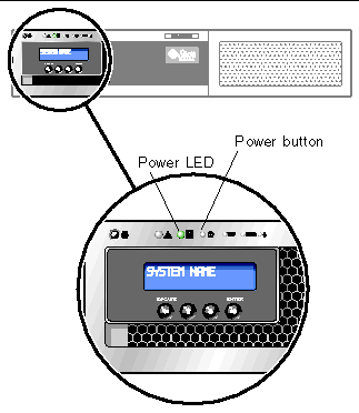
6. Power on server H1 (software serial number ending in "-H1") by using a pen tip or similar implement to press the recessed Power button (FIGURE 4-10).

|
Caution - Do not power up server H2 until directed in the instructions that follow. |
7. Verify that server H1 has finished booting up, as indicated by the LCD display "QUIET."
8. To complete the power-on sequence, continue with the next section, Initial Sun StorageTek 5320 NAS Cluster Appliance Configuration.
|
|
Note - If you have a controller unit and one or more expansion units, you must use this initial power-on sequence. If you do not have any expansion units, you must use the procedure described in To Initially Power On the Sun StorageTek 5320 NAS Cluster Appliance and Controller Unit. |
1. Verify that all cables between the Sun StorageTek 5320 NAS Cluster Appliance and controller units are properly secured according to the instructions in Connecting the Sun StorageTek 5320 NAS Cluster Appliance to Controller Units.
2. Verify that the Cat5 Ethernet cable is connected between the heartbeat ports according to the instructions in Connecting the Server Health-Monitoring and Network Cables.
3. Power on each controller unit by setting the two power supply switches to the On position, and wait at least 3 minutes for all controllers to completely power on.
4. After 3 minutes, check that all LEDs on the controller unit front panels have turned solid green, indicating good operation.
5. Power on the first expansion unit by setting the two power supply switches to the On position.
6. Check that all LEDs on the expansion unit front panel have turned solid green, indicating good operation.
7. Power on any additional expansion units one at a time, making sure that all LEDs on the front panel of each unit turn solid green and waiting at least 30 seconds before you power on the next unit.
8. After all expansion units have been properly powered on, wait 5 minutes, then proceed to Step 9.
9. Verify that the appliance is connected to the network.
10. Power on server H1 (software serial number ending in "-H1") by using a pen tip or similar implement to press the recessed Power button. Refer to FIGURE 4-10 for a detailed illustration of the front panel.

|
Caution - Do not power up server H2 until directed in the instructions that follow. |
11. Verify that server H1 has finished booting up, as indicated by the LCD display "QUIET."
12. To complete the power-on sequence, continue with the next section, Initial Sun StorageTek 5320 NAS Cluster Appliance Configuration.
|
|
Note - Use this procedure if you need to power on the system again after it has been initially powered on. If the system has never been powered on before, use the procedure described in To Initially Power On the Sun StorageTek 5320 NAS Cluster Appliance and Controller Unit or To Initially Power On the Sun StorageTek 5320 NAS Cluster Appliance, Controller Unit, and Expansion Unit. |

|
Caution - When you power off the controller units and expansion units, wait 5 seconds before you power them back on. If you power the units off and on too quickly, unexpected results can occur. |
1. Verify that all cables between the Sun StorageTek 5320 NAS Cluster Appliance, controller units, and expansion units are properly secured according to the instructions in Connecting the Sun StorageTek 5320 NAS Cluster Appliance to Controller Units and Connecting the Controller Units to Expansion Units.
2. Verify that the Cat5 Ethernet cable is connected between the heartbeat ports according to the instructions in Connecting the Server Health-Monitoring and Network Cables.
3. Power on each expansion unit by setting the two power supply switches to the On position. Wait at least 30 seconds before powering on each expansion unit.
|
Note - If the expansion unit contains SATA disk drives, only the Power LED turns solid green. The drive LEDs turn solid green only after the controller unit is powered on. |
4. Power on each controller unit by setting the two power supply switches to the On position.
5. Check that all LEDs on the controller unit front panels have turned solid green, indicating good operation.
6. Check that all LEDs on the expansion unit front panels have turned solid green, indicating good operation.
7. Verify that the Sun StorageTek 5320 NAS Cluster Appliance is connected to the network.
8. Power on server H1 (software serial number ending in "-H1") by using a pen tip or similar implement to press the recessed Power button. Refer to FIGURE 4-10 for a detailed illustration of the front panel.

|
Caution - Do not power up server H2 until directed in the instructions that follow. |
9. Verify that server H1 has finished booting up, as indicated by the LCD display "QUIET."
10. To complete the power-on sequence, continue with the next section, Initial Sun StorageTek 5320 NAS Cluster Appliance Configuration.
To complete the initial Sun StorageTek 5320 NAS Cluster Appliance configuration, you must specify the following:
|
You assign a static IP address using the server H1's LCD panel.
3. Select A. Set Gateway and enter the gateway address.
To enter data, use the up and down arrow buttons to change digits and press the ENTER button to confirm each digit. The cursor moves to the next digit. Once the last digit is set, press the ENTER button again to proceed to the next network setting. After the broadcast address is set, press the ENTER button to return to the Network Config menu.
4. Select C. Set Port-emc2 and enter the IP address, subnet mask, and broadcast address as prompted.
This IP address information is assigned to the first regular (non-heartbeat) LAN port, emc2, on your system.

|
Caution - Do not change the private IP address on the network port that is used for the HB Port (heartbeat port). |
5. Select Escape twice to return to the main menu.
|
Note - If you would like to verify your settings on the LCD panel, HB Port shows a private IP address, and Port emc2 (the first regular LAN port) shows the information you just entered. |
You can edit the port information and assign addresses to other ports in the same way.
6. From server H1's LCD menu, select C. Take All LUNs and press the ENTER button.
7. When prompted to "take all LUNs," press the up arrow button to select "Yes," and press the ENTER or right arrow button to start taking LUNs.
The LCD displays "Taking LUNs" followed by a message "Took n LUNs." After a few seconds, the display returns to the Network Config menu.
8. Select Escape to return to the main menu.
Server H1 is now in the ALONE state.
9. Power on the server H2 (software serial number ending in "-H2") by pressing the recessed Power button.
10. Wait until server H2's LCD display status is QUIET.
11. Use the instructions in Step 1 through Step 5 to assign server H2's IP address and gateway address.
|
To configure the system using the Web Admin application, follow these instructions:
1. From a client on the same network, open a Java platform-enabled web browser with Java Plug-in and enter the IP address for server H1.
2. Accept the "Applet Security Certificate" and wait until the Web Admin applet is loaded on this system.
3. On the Web Admin login screen, click Apply.
The password can be set later. Refer to the Sun StorageTek 5320 NAS OS Administration Guide.
4. On the Set Time and Date panel, select the date, the time, and the time zone, and click Apply. Then click Yes to confirm.
This sets the secure clock to the same time and date. Make sure you set the time and date accurately as you can set the secure clock only once.
5. Read the license agreement in the Configuration wizard dialog box, and click Accept.
6. Click Next in the Welcome dialog box, and proceed with the following steps:
a. From the Select Environment screen, configure Microsoft Windows, UNIX, or both environments, and click Next to continue.
b. From the Set Server Name screen, type the server name and populate the other fields accordingly, and then click Next.
c. From the Enable Failover screen, select Automatic Failover and Enable Link Failover.
A default value of 60 seconds is assigned in both the Down Timeout and Restore Timeout fields.
d. Type the Partner Configuration Name and the Gateway IP address for server H2 (Partner Name factory default is "head2"), and click Apply.
The information you enter here is used to start server H2. The Partner Name is the host name you want to assign to server H2. Any network information server H2 obtained manually through the LCD panel is displayed here and can be corrected, if necessary.
The field for Private IP should already be populated and must not be changed.
f. On the Configure Network Adapters screen, verify that the information is correct.
You can configure additional network interfaces at this time. However, if you change the configuration of the port to which the browser is attached, the browser session is disconnected.
h. On the Set Gateway Address screen, verify that the address is correct, and, if not, enter the gateway address. Click Next to continue.
7. For all the other wizard configuration steps, refer to the Sun StorageTek 5320 NAS OS Administration Guide for more information.
|
Note - When adding your DNS server, click Add to ensure the DNS server has been added. |
8. On the Confirmation screen, review the configuration information you have added.
|
Note - Be sure the configuration information is accurate before continuing. |
9. Click Finish on the wizard Confirmation screen.
The system configures the settings and indicates that in the Save Configuration screen. It also displays a message that both servers must reboot for the failover changes to be applied.
10. Click Close on the Save Configuration screen.
|
To finish the configuration process, you must assign LUN ownership for both servers.
1. Launch a new browser window and type server H1's IP address.
2. On the Web Admin login screen, click Apply. A password is not required.
The password can be set later. Refer to the Sun StorageTek 5320 NAS OS Administration Guide.
3. From the navigation panel, select High Availability > Recover.
Check the status of the recover process in the logging window (bottom pane).
4. In the Restore RAID Configuration window, assign some of the LUNs to server H2.
|
Note - You must assign at least one LUN to each server. In most situations, you will want approximately equal amounts of storage assigned to each server in the cluster. |
|
Note - The appropriate LUN assignments are saved in the (New) Restore RAID Configuration window. |
6. Click Recover, and the LUNs are distributed between both the servers.
At this point, both servers change to the NORMAL state.
|
Note - Verify that both servers are in the NORMAL state on the LCD Panel display or on the Web Admin main page, where the Head Status and Partner Status should display NORMAL. |
|
You need to assign LUN paths on each server to balance multipath access from each server to each storage controller.
Refer to the Sun StorageTek 5320 NAS OS Administration Guide for additional information about manually assigning LUN paths and other detailed software setup and use.
|
For server H2, repeat all steps in To Configure the System with the following exceptions:
Copyright © 2007, Sun Microsystems, Inc. All Rights Reserved.