C H A P T E R  4

Specifications and Connectors

This chapter provides the specifications and connector pinouts for the ARTM-HD.

This chapter contains the following sections:


4.1 Specifications for the ARTM-HD

This section provides mechanical, electrical, environmental, and other relevant specifications for the ARTM-HD.

4.1.1 Physical Dimensions

The ARTM-HD is a 6U (233.35 mm) height board with 80 mm in depth for standard applications. It complies with IEEE 1101.11 mechanical standards, as required by the PICMG 3.0 Revision 2.0 specification. The ARTM-HD is keyed to conform to the PICMG 2.10, Keying of ATCA Boards and Backplanes specification.

4.1.2 Power Requirements

The power consumption of the ARTM-HD is limited to 25W maximum. The blade server provides the following voltages: 3.3V Management Power and +12V Payload Power. The ARTM-HD creates 3.3V, 5V, and 1.2V from the 12v Payload Power.

4.1.3 Electrical Requirements

The ARTM-HD is powered through the Sun Netra ATCA node blade server. The blade server provides the following voltages: 3.3V/+12V.

4.1.4 Environmental Specifications and Compliance

For details on the environmental specifications and compliance, see Important Safety Information for Sun Hardware Systems (816-7190), the Sun Netra CP3220 Blade Server User’s Guide (820-1982).

You can download and view these documents from the following web site:

http://www.sun.com/documentation/


4.2 Hardware Descriptions

4.2.1 Ethernet Management Port

The ARTM-HD provides one 10/100/1000 MBASE-T ethernet management port with an RJ-45 connector equipped with LEDs.

4.2.2 Infinband-style Connectors

The ARTM-HD provides two (primary and secondary) Infinband-style SAS connectors, with jack screws, for external drive support using a SFF-8470 style SAS cable.

4.2.3 Serial Port

One asynchronous serial port with an RJ-45 serial connector is included on the ARTM-HD I/O faceplate. The serial port may be redirected to the front blade server when using a Sun Netra CP3220 blade server, a Sun Netra CP3260 blade server, or other ARTM -compatible blade server. For more information on using both the front and rear serial ports, refer to the appropriate blade server documentation.

4.2.4 SAS Interface

The ARTM-HD includes a LSI 1068E PCIe to 8-port SAS controller chip.

4.2.5 Module Management Controller

The onboard Module Management Controller (MMC) provides IPMI management communication between the RTM and the blade server, and local monitoring of temperature and voltage.

4.2.6 FRU PROM

The ARTM-HD contains an IPMI FRU Prom compatible with the ATCA specifications.


4.3 Connectors and Pin Assignments

FIGURE 4-1 shows the location of the connectors.

FIGURE 4-1 Sun Netra CP32x0 ARTM-HD Connectors
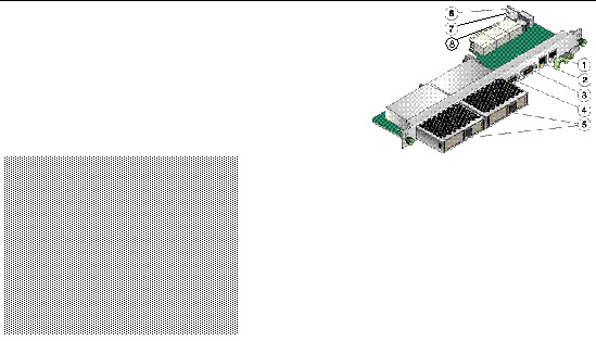

Figure showing the location of the connectors and pins on the Sun Netra CP32x0 advanced rear transition module


1 - Serial port

5 - Hard disk drive(s) (single drive contains a filler panel on the second drive)

2 - 10/100/1000 Mb Management port

6 - RTM alignment pin

3 - External SAS port (secondary)

7 - Power connector

4 - External SAS port (primary)

8 - Zone 3 connectors


4.3.1 I/O Connectors

This section lists the pins and signal names of the I/O faceplate connectors on the ARTM-HD. The faceplate has the following connectors:

4.3.1.1 Ethernet Port

The Ethernet connector is an RJ-45 connector with LEDs. The controller autonegotiates to either 10/100/1000BASE-T. FIGURE 4-2 shows an Ethernet RJ-45 connector.

FIGURE 4-2 Ethernet RJ-45 Connector
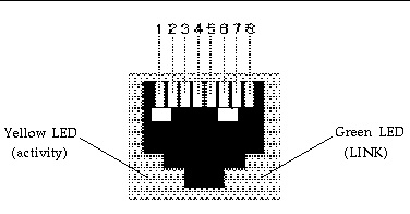

Figure showing the LEDs on the Sun Netra CP32x0 advanced rear transition module.

TABLE 4-1 gives the pin assignments for the Ethernet ports.


TABLE 4-1 Ethernet Port Connector Pin Assignments

Pin

Signal Name

Pin

Signal Name

1

DA+

5

DC-

2

DA-

6

DB-

3

DB+

7

DD+

4

DC+

8

DD-


4.3.1.2 Serial Port

The serial port connector is an RJ45 connector. FIGURE 4-3 shows a serial port connector.

FIGURE 4-3 Serial Port Connector
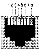

Figure showing a serial port Rs232 connector and pin numbers.

TABLE 4-2 gives the serial port connector pin assignments.


TABLE 4-2 Serial Port Connector Pin Assignments

Pin

Signal Name

Pin

Signal Name

1

RTS

5

GND

2

DTR

6

RXD

3

TXD

7

DSR

4

GND

8

CTS


4.3.1.3 SAS Connectors

The ARTM-HD provides two Serial Attached SCSI (SAS) ports using an Infinband-style connector.
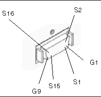
FIGURE 4-4 SAS Connectors


Figure showing an illustration of the SAS connectors on the Sun Netra CP32x0 ARTM-HD..


TABLE 4-3 External SAS Connector Pin Assignments

Pin

Function

S1

RX0+

S2

RX0-

S3

RX1+

S4

RX1-

S5

RX2+

S6

RX2-

S7

RX3+

S8

RX3-

S9

TX3-

S10

TX3+

S11

TX2-

S12

TX2+

S13

TX1-

S14

TX1+

S15

TX0-

S16

TX0+

G1-9

Signal Ground

Housing

Chassis Ground


4.3.2 Zone 3 Connectors

All the I/O connections for rear access are provided by the Sun Netra blade server through the Zone 3 connectors. The Zone 3 connectors are P31, P32, and P33. The Zone 3 connectors are shown in FIGURE 4-5.


Note - The letters TX in a pin name indicate that the signal is transmitted from the ATCA card to the ARTM card.


FIGURE 4-5 Zone 3 Connectors


Figure showing the Zone 3 connectors and pin layouts.

TABLE 4-4 lists the Zone 3, J31 connector pinouts.


TABLE 4-4 J31 Connector Pin Assignments

Row

Interface

A

B

C

D

E

F

1

AMC1 EO Ports

TX1_13+

TX1_13-

RX1_12+

RX1_12-

TX1_12+

TX1_12-

2

RX1_14+

RX1_14-

TX1_14+

TX1_14-

RX1_13+

RX1_13-

3

TX1_17+

TX1_17-

RX1_15+

RX1_15-

TX1_15+

TX1_15-

4

RX1_18+

RX1_18-

TX1_18+

TX1_18-

RX1_17+

RX1_17-

5

TX1_20+

TX1_20-

RX1_19+

RX1_19-

TX1_19+

TX1_19-

6

RX2_12+

RX2_12-

TX2_12+

TX2_12-

RX1_20+

RX1_20-

7

AMC2 EO Ports

TX2_14+

TX2_14-

RX2_13+

RX2_13-

TX2_13+

TX2_13-

8

RX2_15+

RX2_15-

TX2_15+

TX2_15-

RX2_14+

RX2_14-

9

TX2_18+

TX2_18-

RX2_17+

RX2_17-

TX2_17+

TX2_17-

10

RX2_19+

RX2_19-

TX2_19+

TX2_19-

RX2_18+

RX2_18-


TABLE 4-5 lists the Zone 3, J32 connector pinouts.


TABLE 4-5 J32 Connector Pin Assignments

Row

Interface

A

B

C

D

E

F

1

AMC2 EO Ports

NC

NC

RX2_20+

RX2_20-

TX2_20+

TX2_20+

2

SAS/SATA0 - SER0

SA_TX0+

SA_TX0-

SA_RX0+

SA_RX0-

SR0_RTS

SR0_DTR

3

SAS/SATA1 - SER0

SA_TX1+

SA_TX1-

SA_RX1+

SA_RX1-

SR0_TXD

SR0_RXD

4

SAS/SATA2 - SER0

SA_TX2+

SA_TX2-

SA_RX2+

SA_RX2-

SR0_DSR

SR0_CTS

5

SAS/SATA3 - SER0

SA_TX3+

SA_TX3-

SA_RX3+

SA_RX3-

NC

NC

6

LAN0 (MNGT)

LAN0_A+

LAN0_A-

LAN0_CTV

LAN0_CTV

LAN0_B+

LAN0_B-

7

LAN0_C+

LAN0_C-

ACT_LED#

LINK_LED#

LAN0_D+

LAN0_D-

8

LAN1 (SerDes)

SLAN_TX1+

SLAN_TX1-

SLAN_RX1+

SLAN_RX1-

NC

NC

9

LAN2 & LAN4 (SerDes)

SLAN_TX2+

SLAN_TX2-

SLAN_RX2+

SLAN_RX2-

SLAN_TX4+

SLAN_TX4-

10

LAN3 & LAN4 (SerDes)

SLAN_TX3+

SLAN_TX3-

SLAN_RX3+

SLAN_RX3-

SLAN_RX4+

SLAN_RX4-


TABLE 4-6 lists the Zone 3, J33 connector pinouts.


TABLE 4-6 J33 Connector Pin Assignments

Row

Interface

A

B

C

D

E

F

1

PCIe x8 Lane

PETx0+

PETx0-

PERx0+

PERx0-

FCLKA+

FCLKA-

2

PETx1+

PETx1-

PERx1+

PERx1-

TCLKA+

TCLKA-

3

PETx2+

PETx2-

PERx2+

PERx2-

TCLKB+

TCLKB-

4

PETx3+

PETx3-

PERx3+

PERx3-

TCLKC+

TCLKC-

5

PETx4+

PETx4-

PERx4+

PERx4-

TCLKD+

TCLKD-

6

PETx5+

PETx5-

PERx5+

PERx5-

TCK

TMS

7

PETx6+

PETx6-

PERx6+

PERx6-

TRST#

TDO

8

PETx7+

PETx7-

PERx7+

PERx7-

TDI

PCI_RST#

9


NC

NC

NC

NC

RTM#

PCI_CFG

10


NC

NC

NC

NC

PS0#

Enable#