C H A P T E R  1

Feedback Sun Rack 1000 and Sun Rack 900 Cabinets

The Sun Rack 1000 and the Sun Rack 900 cabinets can enclose Sun SPARC Enterprise M3000/M4000/M5000 servers, storage products, and qualified third-party equipment.

This document contains the following sections:


1.1 Technical Information

The Sun Rack 1000 comes as a 42-rack unit (U) or a 38U enclosure. The Sun Rack 900 comes as a 38U or 36U enclosure. Entry-level and midrange servers can be mounted or preinstalled in these equipment cabinets.


Note - The Sun Rack 1000/900 cabinets have round RETMA rail holes.


FIGURE 1-1 illustrates Sun Rack 1000/900 with one modular power supply (MPS) and Two MPSs.

FIGURE 1-1 Sun Rack 900 With Modular Power Supplies
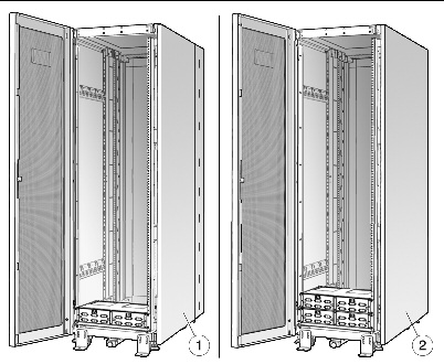

Figure shows Sun Rack 900 with modular power supplies.


Figure Legend

1

Sun Rack 900 With One Modular Power Supply

2

Sun Rack 900 With Two Modular Supplies


1.1.1 Physical Specifications

Use the following table to determine space requirements for the Sun Rack 1000 and the Sun Rack 900.


TABLE 1-1 Sun Rack 1000 Dimensions

Characteristic

42U

38U

Height

2019 mm/79.5 in.

1880 mm/74 in.

Width

597 mm/23.5 in.

597 mm/23.5 in.

Depth

1000 mm/39.8 in.

1000 mm/39.8 in.

Weight

193 kg/426 lb

168 kg/370 lb


Table listing Sun Rack 1000 dimensions.


TABLE 1-2 Sun Rack 900 Dimensions

Characteristic

38U

36U

Height

1880 mm/74 in.

1880 mm/74 in.

Width

597 mm/23.5 in.

597 mm/23.5 in.

Depth

900 mm/35.4 in.

900 mm/35.4 in.

Weight

168 kg/370 lb

172 kg/380 lb


Table listing Sun Rack 900 dimensions.

FIGURE 1-2 illustrates the Sun Rack 1000 42U shipping crate dimensions.

FIGURE 1-2 Sun Rack 1000- 42/38-Rack Unit Shipping Dimensions
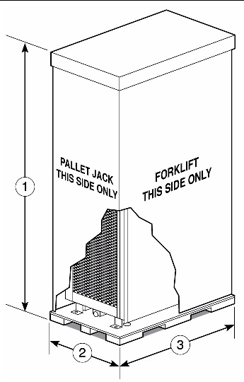

Figure showing Sun Rack 1000-42/38 rack unit shipping dimensions.


Figure Legend

1

Height, 2184 mm/86 in.

2

Width, 1080 mm/42.5 in.

3

Depth, 1506 mm/59.3 in.


FIGURE 1-3 illustrates the top and front dimensions of a Sun rack.

FIGURE 1-3 Sun Rack 900 With Cabinet Extender Top and Front Dimensions
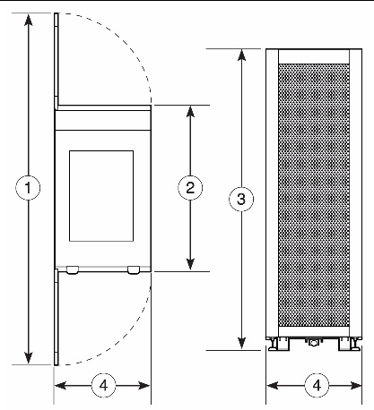

Figure showing Sun Rack 900 with cabinet extender top and front dimensions.


Figure Legend

1

Length, doors open, 2194 mm/86.4 in.

2

Length, doors closed, 1000 mm/35.4 in.

3

Height, 1880 mm/74 in.

4

Width, 597 mm/23.5 in.


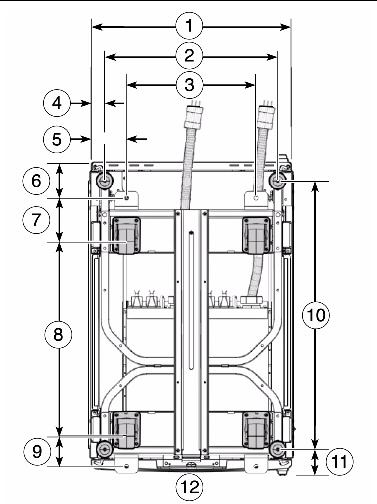
FIGURE 1-4 and FIGURE 1-5 illustrate the footprint of a Sun Rack 1000 and Sun Rack 900.

FIGURE 1-4 Sun Rack 1000 Bottom View
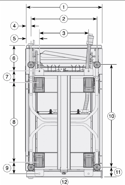

Figure showing the physical dimensions of the bottom of the SunRack 1000.


Figure Legend

1

Cabinet width, 599 mm/23.6 in.

7

Depth, hole to caster center, 90 mm/3.5 in.

2

Width between pad centers, 516 mm/20.3 in.

8

Depth between casterx, 620 mm/24.4 in.

3

Width between holes, 386 mm/15.2 in.

9

Depth, caster to hole, 90 mm/3.5 in.

4

Width, side to pad center, 42 mm/1.7 in.

10

Depth between pads, 800 mm/31.5 in.

5

Width, side to hole, 107 mm/4.2 in.

11

Depth, pad to rear, 50 mm/2 in.

6

Depth, front to hole, 200 mm/7.9 in.

12

Front of cabinet


FIGURE 1-5 Sun Rack 900 Bottom View


Figure showing the physical dimensions of the bottom of the SunRack 900.


Figure Legend

1

Cabinet width, 599 mm/23.6 in.

7

Depth, hole to caster center, 100 mm/3.9 in.

2

Width between pad centers, 516 mm/20.3 in.

8

Depth between casterx, 620 mm/24.4 in.

3

Width between holes, 386 mm/15.2 in.

9

Depth, caster to hole, 90 mm/3.5 in.

4

Width, side to pad center, 42 mm/1.7 in.

10

Depth between pads, 800 mm/31.5 in.

5

Width, side to hole, 107 mm/4.2 in.

11

Depth, pad to rear, 50 mm/2 in.

6

Depth, front to hole, 90 mm/3.5 in.

12

Front of cabinet


1.1.2 Electrical Specifications

TABLE 1-3 and TABLE 1-4 display system electrical specifications and receptacle model numbers.


TABLE 1-3 Sun Cabinet (Modular Power System) Electrical Specifications--Americas, Japan, Taiwan

Parameter


Value

Input current

Voltage range

Current, maximum

Current frequency range

208 VAC three phase

45A at 208 VAC per phase

50-60 Hz

Volt-Ampere rating


16200 VA


Connector type

North American, Japan, Taiwan

2 60A IEC 309 4 Pin for 208 VAC three phase, preinstalled with the cabinet

Receptacle type

North American, Japan, Taiwan

2 60A IEC 309 4 Pin for 208 VAC three phase, Hubbell C460P9W or equivalent


TABLE 1-4 Sun Cabinet (Modular Power System) Electrical Specification--Other Countries

Parameter


Value

Input current

Voltage range

Current, maximum

Current frequency range

230/400 VAC three phase

32A per phase

50-60 Hz

Volt-Ampere rating


Connector type


Other

22080 VA


2 32A IEC 309 5 Pin for 230/400 VAC three phase, preinstalled with the cabinet.

Receptacle type

Other

2 32A IEC 309 5 Pin for 230/400 VAC three phase, Hubbell C532R6S or equivalent


1.1.3 Vibration Limitations

TABLE 1-5 lists the allowable vibration for M3000/M4000/M5000 servers in a Sun Rack 1000/900.


TABLE 1-5 Allowable Vibration for the M3000/M4000/M5000 Servers

Operating

Non-Operating

Vertical: 0.15g

Horizontal: 0.10g

5 to 500 Hz, swept-sine

Vertical: 3.0 mm pk-pk/0.5g,

5 to 500 Hz, swept-sine

Horizontal: 3.0 mm pk-pk/0.25g,

5 to 500 Hz, swept-sine


Table listing the allowable vibration for M3000/M4000/M5000 server in a Sun Rack 1000/900.

1.1.4 Space and Thermal Specifications

For maintenance access, entry-level and midrange servers in racks require a minimum of four feet to the front, three feet to the rear, and three feet from the top. racks can be placed next to each other since there are no side clearance requirements during operation.

Both entry-level and midrange servers must maintain the minimum thermal distance between the rear of the server in an rack (914 mm/36 in.) and any obstructions or walls.

1.1.5 Service Area

The Sun SPARC Enterprise M3000/M4000/M5000 servers are accessed from the top surfaces. A stepladder may be required for maintenance depending upon the height these servers are mounted in the cabinet. Ensure an adequate service area for maintenance work.

FIGURE 1-6 Front and Rear Maintenance Access and Thermal Specifications
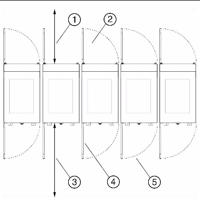

Figure showing front and rear maintenance access and thermal specifications.


Figure Legend

1

914 mm (36 inches) access at rear

2

Rear door

3

1219 mm (48 inches) access at front

4

Front door

5

914 mm (36 inches) access from the top


1.1.6 Access Route

If your existing loading dock meets height or ramp requirements for a standard freight carrier truck, you can use a pallet jack to unload the server. If not, you must provide a standard forklift or other means to unload the server, or request the server be shipped in a truck with a lift gate.

All servers not shipped in an rack should be lifted only by proper computer-lifting equipment to prevent personal injury or damage to server equipment.

Each server that is not preinstalled in an rack is shipped in a separate crate. A pallet jack is required to move each shipping crate to the server location.

Leave each server in its shipping crate until it reaches its final destination. If the crate does not fit through the planned access route, partially disassemble it.

The entire access route to your computer room should be free of raised patterns that can cause vibration, and the route must meet the requirements listed in TABLE 1-6.


TABLE 1-6 Access Route Requirements

With Shipping Pallet

Without Shipping Pallet

Minimum door height

2184 mm/86 in.

2019 mm/79.5 in.

Minimum elevator depth

1506 mm/59.3 in.

1506 mm/59.3 in.

Maximum incline

10˚

10˚


Minimum elevator, pallet jack, and floor loading capacity
(maximum weight per server)

544 kg (1200 lb)


Table listing access route requirements.

1.1.7 Server Guidelines

As you plan your space needs for the Sun racks, keep these conditions in mind:


1.2 Mounting Specifications

The Sun Rack 1000/900 can enclose up to twenty-one 2U M3000 servers, six 6U M4000 servers and three 10U M5000 servers. If you are mounting servers in a Sun Rack 900, an optional cabinet extender is available to extend the depth of the rack from the rear to enable the door to close.

1.2.1 Installing the Cabinet Extender (Optional)

1. Remove the rear door of the rack and set it aside.

2. Place the cabinet extender onto the door hinge pins at the rear of the rack and secure in place. (FIGURE 1-7)

3. Mount the rear door on the cabinet extender.


FIGURE 1-7 Installing the Cabinet Extender
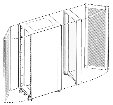

Figure showing how to install the Cabinet Extender.


1.3 Stabilizing the Cabinet

The Sun cabinet can be permanently mounted to the floor using the same brackets that secured the cabinet to the shipping pallet. The cabinet side of the mounting brackets are slotted to allow for vertical positioning.

FIGURE 1-8 illustrates a mounting bracket on a Sun Rack 1000 and the hole spacing required to secure the cabinet permanently to the floor.

FIGURE 1-8 Sun Rack 1000 Mounting Brackets and Hole Spacing for Floor Mounting
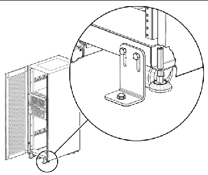

Figure showing Sun Rack 1000 mounting brackets and hole spacing for floor mounting.

FIGURE 1-9 Hole Spacing for Floor Mounting
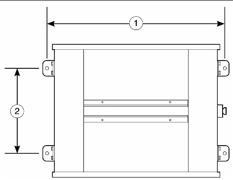

Figure showing hole spacing for floor mounting.


Figure Legend

1

Width, 1000 mm/39.5 in.

2

Depth, 388 mm/15.2 in.


Feedback